
Page 474 - Wind Energy Handbook
P. 474
448 COMPONENT DESIGN
900
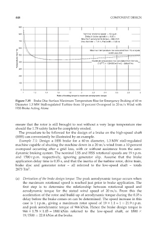
800 Nominal rotational speed = 19 r.p.m.
Delay in brake operation = 0.35 s
Maximum aerodynamic torque = 966 kNm
700 Disc diameter = 1.0 m, Pad width = 0.22 m
600 Maximum temperature rise calculated from FE analysis
Temperature rise ( C) 500 Maximum temperature rise calculated from formula
- continuous line
400
0.5
E/(t
) x 1/(64600w(D-w)) - dotted line
300
200
100
0
1 1.2 1.4 1.6 1.8 2 2.2 2.4 2.6 2.8 3
Ratio of braking torque to maximum aerodynamic torque
Figure 7.35 Brake Disc Surface Maximum Temperature Rise for Emergency Braking of 60 m
Diameter 1.3 MW Stall-regulated Turbine from 10 percent Overspeed in 20 m/s Wind with
HSS Brake Acting Alone
ensure that the rotor is still brought to rest without a very large temperature rise
should the 1.78 safety factor be completely eroded.
The procedure to be followed for the design of a brake on the high-speed shaft
(HSS) can conveniently be illustrated by an example.
Example 7.1: Design a HSS brake for a 60 m diameter, 1.3 MW stall-regulated
machine capable of shutting the machine down in a 20 m/s wind from a 10 percent
overspeed occurring after a grid loss, with or without assistance from the aero-
dynamic braking system. The nominal LSS and HSS rotational speeds are 19 r.p.m.
and 1500 r.p.m. respectively, ignoring generator slip. Assume that the brake
application delay time is 0.35 s, and that the inertia of the turbine rotor, drive train,
brake disc and generator rotor – all referred to the low-speed shaft – totals
2
2873 Tm .
(a) Derivation of the brake design torque: The peak aerodynamic torque occurs when
the maximum rotational speed is reached just prior to brake application. The
first step is to determine the relationship between rotational speed and
aerodynamic torque for the stated wind speed of 20 m/s. From this the
acceleration of the rotor and build-up of aerodynamic torque during the 0.35 s
delay before the brake comes on can be determined. The speed increase in this
case is 1 r.p.m., giving a maximum rotor speed of 19 3 1:1 þ 1 ¼ 21:9r:p:m:
and peak aerodynamic torque of 966 kNm. Hence the brake design torque is
966 3 1:78 3 1:05 ¼ 1800 kNm referred to the low-speed shaft, or 1800 3
19=1500 ¼ 22:8 kNm at the brake.