
Page 477 - Wind Energy Handbook
P. 477
YAW DRIVE 451
supports the low-speed shaft main bearing at the front and the port and starboard
gearbox supports towards the rear, with the generator mounted on a fabricated
platform projecting to the rear and attached to the main casting by bolts.
Although conventional methods of analysis can be used to design the bedplate
for extreme loads, the complicated shape renders a finite-element analysis essential
for calculating the stress concentration effects needed for fatigue design. Fatigue
analysis is complicated by the need to take into account up to six rotor load
components. However, given stress distributions for each load component obtained
by separate FE analyses, the stress-time history at any point can be obtained by
combining appropriately scaled load component time histories previously obtained
from a load case simulation.
7.8 Yaw Drive
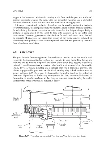
The yaw drive is the name given to the mechanism used to rotate the nacelle with
respect to the tower on its slewing bearing, in order to keep the turbine facing into
the wind and to unwind the power and other cables when they become excessively
twisted. It usually consists of an electric or hydraulic motor mounted on the nacelle,
which drives a pinion mounted on a vertical shaft via a reducing gearbox. The
pinion engages with gear teeth on the fixed slewing ring bolted to the tower, as
shown in Figure 7.37. These gear teeth can either be on the inside or the outside of
the tower, depending on the bearing arrangement, but they are generally located on
the outside on smaller machines so that the gear does not present a safety hazard in
the restricted space available for personnel access.
Nacelle Yaw drive
bedplate gearbox
Yaw
bearing
(with internal
gear)
Brake disc
Yaw drive
pinion
Hydraulic C
Tower Calliper thruster L
wall yaw brake
Tower
Figure 7.37 Typical Arrangement of Yaw Bearing, Yaw Drive and Yaw Brake