
Page 465 - Wind Energy Handbook
P. 465
GENERATOR 439
turbines liquid cooling is used to reduce air-borne noise. A high slip at rated power
output is often requested by the wind turbine designer as this increases the
damping in the wind turbine drive train but at the expense of losses in the rotor.
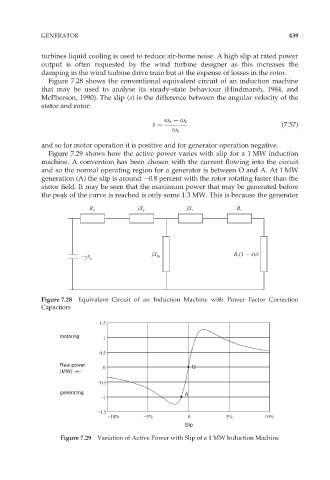
Figure 7.28 shows the conventional equivalent circuit of an induction machine
that may be used to analyse its steady-state behaviour (Hindmarsh, 1984, and
McPherson, 1990). The slip (s) is the difference between the angular velocity of the
stator and rotor:
ø s ø r
s ¼ (7:57)
ø s
and so for motor operation it is positive and for generator operation negative.
Figure 7.29 shows how the active power varies with slip for a 1 MW induction
machine. A convention has been chosen with the current flowing into the circuit
and so the normal operating region for a generator is between O and A. At 1 MW
generation (A) the slip is around 0.8 percent with the rotor rotating faster than the
stator field. It may be seen that the maximum power that may be generated before
the peak of the curve is reached is only some 1.3 MW. This is because the generator
R s jX s jX r R r
jX R (1 s)/s
jX c m r
Figure 7.28 Equivalent Circuit of an Induction Machine with Power Factor Correction
Capacitors
1.5
motoring
1
0.5
Real power
0 O
(MW)
0.5
generating A
1
1.5
10% 5% 0 5% 10%
Slip
Figure 7.29 Variation of Active Power with Slip of a 1 MW Induction Machine