
Page 110 - Wire Bonding in Microelectronics
P. 110
W ir e Bond Testing 89
the h/d ratio increases significantly, yielding a pull force higher than one
would expect if only the breaking load of the wire and the initial bond
geometry were considered. This effect will be even more significant if
the initial value of h was low.
Figure 4-2 showed that loop height is an important factor in deter-
mining the bond pull force. Thus, it is apparent that significant wire
elongation during bond pulling will change the loop height and affect
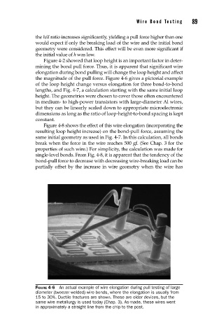
the magnitude of the pull force. Figure 4-6 gives a pictorial example
of the loop height change versus elongation for three bond-to-bond
lengths, and Fig. 4-7, a calculation starting with the same initial loop
height. The geometries were chosen to cover those often encountered
in medium- to high-power transistors with large-diameter Al wires,
but they can be linearly scaled down to appropriate microelectronic
dimensions as long as the ratio of loop-height-to-bond spacing is kept
constant.
Figure 4-8 shows the effect of this wire elongation (incorporating the
resulting loop height increase) on the bond-pull force, assuming the
same initial geometry as used in Fig. 4-7. In this calculation, all bonds
break when the force in the wire reaches 500 gf. (See Chap. 3 for the
properties of such wire.) For simplicity, the calculation was made for
single-level bonds. From Fig. 4-8, it is apparent that the tendency of the
bond-pull force to decrease with decreasing wire-breaking load can be
partially offset by the increase in wire geometry when the wire has
FIGURE 4-6 An actual example of wire elongation during pull testing of large
diameter (tweezer welded) wire bonds, where the elongation is usually from
15 to 30%. Ductile fractures are shown. These are older devices, but the
same wire metallurgy is used today (Chap. 3). As-made, these wires went
in approximately a straight line from the chip to the post.