
Page 115 - Wire Bonding in Microelectronics
P. 115
94 Cha pte r F o u r
Wire
Shoulder
Bonded ball
chip Shear F
tool
Bonding pad
Area of contact
(faying surface)
FIGURE 4-10 Schematic drawing of the ball-shear test. The bonded (welded)
area is often less than the faying area (area of intimate contact). The typical
outside diameter of a bonded ball from a 25 µm (1 mil) diameter Au wire is
from about 50 to 100 µm (3.0 to 4.5 mil). The height of the ball above the
bonding pad is usually less than 25 µm (1 mil) but << for fi ne pitch.
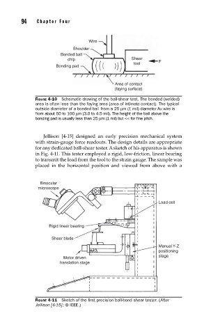
Jellison [4-15] designed an early precision mechanical system
with strain-gauge force readouts. The design details are appropriate
for any dedicated ball-shear tester. A sketch of his apparatus is shown
in Fig. 4-11. This tester employed a rigid, low-friction, linear bearing
to transmit the load from the tool to the strain gauge. The sample was
placed in the horizontal position and viewed from above with a
Binocular
microscope
Load cell
Rigid linear bearing
Shear blade
Manual Y-Z
positioning
stage
Motor driven
translation stage
FIGURE 4-11 Sketch of the fi rst precision ball-bond shear tester. (After
Jellison [4-15] ; © IEEE.)