
Page 117 - Wire Bonding in Microelectronics
P. 117
96 Cha pte r F o u r
See detail A
0.6 cm
dia.
12 cm 2.5
cm
Hand held
0.25 mm Detail A shear tool
F
Ball
0.13
20–25%
mm
Top view 20–25% angle
0.08 mm
Side view ~6 µm
0.25 mm
radius
Detailed sketch of manual Sketch of manual shear
ball shear probe probe in use
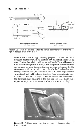
FIGURE 4-12 Left is the detailed sketch of a manual ball shear probe and to the
right is a sketch of the probe in use.
bond is then contacted approximately perpendicular to its radius. A
binocular microscope with no less than 30X magnification should be
used. Practice should start with strong ball bonds. These will generally
have a shear force greater than 50 gf. For comparison, some weak balls
can be made by using the same bonding-machine settings as for the
strong ones but locating half or more of the ball off the bonding pad.
If the pads are on an IC, this will place part of the bond on passivation
where it will not weld, reducing the shear force proportionately. An
indication of the bond strength can often be obtained by observing
the deformation or smearing of the ball (see Fig. 4-13). (Such tech-
niques are appropriate for a variety of experiments on bonding.)
FIGURE 4-13 Ball bond on pad lower than polyimide or other passivation
(hard to shear).