
Page 121 - Wire Bonding in Microelectronics
P. 121
100 Cha pte r F o u r
shear test evaluation of compound-thermosonic bonds [4-24].This
work found that centering of the top ball bond on the bottom ball
was very important. There was an increased tendency to crater
in cases where the top ball bond was misaligned on the bottom
one (as revealed by the ball-shear test). Some bonding machines
resulted in more craters than others without apparent reason.
Increased ultrasonic energy also significantly increased crater-
ing, which is normally to be expected. However, when ball on ball
cratering occurred, the energy could be minimized (also tempera-
ture increased) and essentially cure the cratering problem. When
optimized, the bond shear force of the lower ball was statistically
unchanged from that of a single ball bond. Therefore, the use of
compound bonds on chips, made with manual bonders, should
be minimized. Autobonders precisely center a ball on a ball, and
craters from them have not been observed. Stacked ball bonds
made by autobonders are used in making compound ball bonds for
use as standoff bumps when converting devices with Al bond pads
into flip chips (ball bumped flip chips). In most cases, only one ball
bond is used, but there are examples of stacking several to obtain
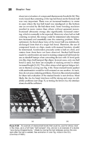
increased height [4-24]. This offers stress relief against fatigue fail-
ure in thermal cycling (see Fig. 4-16). These stacked bonds applied
with autobonders would be well centered on one another. As such,
they do not pose cratering problems. However, the correct procedure
for shear test evaluation of the stacked bonds is not obvious. Most
likely, the Au-Au bond interfaces will be strong and cause no reli-
ability problems (see Chap. 5), so testing the lower (Au-Al) interface
alone should be suffi cient.
(a) (b)
FIGURE 4-16 An example of stacked-ball bonds that could be used for stress relief
in fl ip chips. (a) is a full triple “ball bumped” chip, and (b) is an example of a double
“accu-bump/chopped-bump.” (Made by moving the tool sideways across the wire
neck after the ball is welded. See animation in color Fig. 4-16a in the CD.)
(Courtesy of K&S.)