
Page 123 - Wire Bonding in Microelectronics
P. 123
102 Cha pte r F o u r
Bonded area diameter (µm)
25 38 50 75 100 150 200
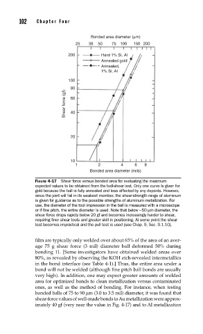
200 Hard 1% Si, Al
Annealed gold
Annealed,
1% Si, Al
100
80
Shear force (gf) 60
40
20
10
1 2 4 6 8
Bonded area diameter (mils)
FIGURE 4-17 Shear force versus bonded area for evaluating the maximum
expected values to be obtained from the ball-shear test. Only one curve is given for
gold because the ball is fully annealed and less affected by any dopants. However,
since the joint will fail in its weakest member, the shear-strength range of aluminum
is given for guidance as to the possible strengths of aluminum metallization. For
use, the diameter of the tool impression in the ball is measured with a microscope
or if fi ne pitch, the entire diameter is used. Note that below ~50 µm diameter, the
shear force drops rapidly below 20 gf and becomes increasingly harder to shear,
requiring fi ner shear tools and greater skill in positioning. At some point the shear
test becomes impractical and the pull test is used (see Chap. 9, Sec. 9.1.10).
film are typically only welded over about 65% of the area of an aver-
age 75 g shear force (3 mil) diameter ball deformed 50% during
bonding 11. [Some investigators have obtained welded areas over
80%, as revealed by observing the KOH etch-revealed intermetallics
in the bond interface (see Table 4-1).] Thus, the entire area under a
bond will not be welded (although fine pitch ball bonds are usually
very high). In addition, one may expect greater amounts of welded
area for optimized bonds to clean metallization versus contaminated
ones, as well as the method of bonding. For instance, when testing
bonded balls of 75 to 90 µm (3.0 to 3.5 mil) diameter, it was found that
shear-force values of well-made bonds to Au metallization were approx-
imately 40 gf (very near the value in Fig. 4-17) and to Al metallization