
Page 105 - Wire Bonding in Microelectronics
P. 105
84 Cha pte r F o u r
10
9 8
Bond pull force (gf) 7 Pull hook for peel
6
Experiment Peel
Failure
5 Theory
4
0 0.25 0.5 0.75 1.0
Position of hook ( )
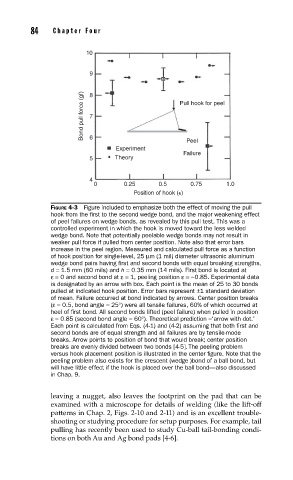
FIGURE 4-3 Figure included to emphasize both the effect of moving the pull
hook from the fi rst to the second wedge bond, and the major weakening effect
of peel failures on wedge bonds, as revealed by this pull test. This was a
controlled experiment in which the hook is moved toward the less welded
wedge bond. Note that potentially peelable wedge bonds may not result in
weaker pull force if pulled from center position. Note also that error bars
increase in the peel region. Measured and calculated pull force as a function
of hook position for single-level, 25 µm (1 mil) diameter ultrasonic aluminum
wedge bond pairs having fi rst and second bonds with equal breaking strengths,
d = 1.5 mm (60 mils) and h = 0.35 mm (14 mils). First bond is located at
ε= 0 and second bond at ε= 1, peeling position ε= ~0.85. Experimental data
is designated by an arrow with box. Each point is the mean of 25 to 30 bonds
pulled at indicated hook position. Error bars represent ±1 standard deviation
of mean. Failure occurred at bond indicated by arrows. Center position breaks
(ε= 0.5, bond angle = 25°) were all tensile failures, 60% of which occurred at
heel of fi rst bond. All second bonds lifted (peel failure) when pulled in position
ε= 0.85 (second bond angle = 60°). Theoretical prediction =‘arrow with dot.’
Each point is calculated from Eqs. (4-1) and (4-2) assuming that both fi rst and
second bonds are of equal strength and all failures are by tensile-mode
breaks. Arrow points to position of bond that would break; center position
breaks are evenly divided between two bonds [4-5]. The peeling problem
versus hook placement position is illustrated in the center fi gure. Note that the
peeling problem also exists for the crescent (wedge )bond of a ball bond, but
will have little effect if the hook is placed over the ball bond—also discussed
in Chap. 9.
leaving a nugget, also leaves the footprint on the pad that can be
examined with a microscope for details of welding (like the lift-off
patterns in Chap. 2, Figs. 2-10 and 2-11) and is an excellent trouble-
shooting or studying procedure for setup purposes. For example, tail
pulling has recently been used to study Cu-ball tail-bonding condi-
tions on both Au and Ag bond pads [4-6].