Page 102 - Wire Bonding in Microelectronics
P. 102

W ir e Bond Testing   81


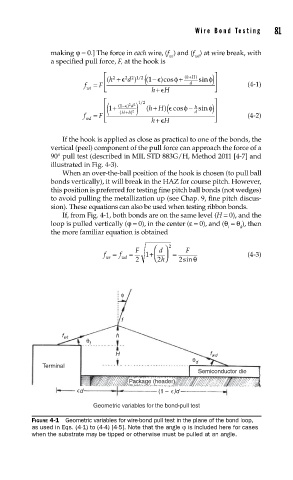
              making ϕ = 0.] The force in each wire, (f ) and (f ) at wire break, with
                                              wt     wd
              a specified pull force, F, at the hook is
                              ( h +   2 2 1 /2  − ( (1   )cosφ  +  ( hH)  sin  ) φ  
                                                    +
                               2
                                   d )
                       f wt  =  F                 d            (4-1)
                                         h+   H
                                    22  12                
                                      /
                                          +
                             (   1 +  1 ( Hh )  ( hH ( ) cos    φ − sinφ )
                                    d
                                 − )
                                                     h
                                    2
                                                     d
                       f wd  =  F    (  + )  +                  (4-2)
                                         h+  H
                 If the hook is applied as close as practical to one of the bonds, the
              vertical (peel) component of the pull force can approach the force of a
              90° pull test (described in MIL STD 883G/H, Method 2011 [4-7] and
              illustrated in Fig. 4-3).
                 When an over-the-ball position of the hook is chosen (to pull ball
              bonds vertically), it will break in the HAZ for course pitch. However,
              this position is preferred for testing fine pitch ball bonds (not wedges)
              to avoid pulling the metallization up (see Chap. 9, fine pitch discus-
              sion). These equations can also be used when testing ribbon bonds.
                 If, from Fig. 4-1, both bonds are on the same level (H = 0), and the
              loop is pulled vertically (ϕ = 0), in the center (ε = 0), and (θ  = θ ), then
                                                              t   d
              the more familiar equation is obtained
                                              2
                            f  =  f  =  F  1 +   d   =  F       (4-3)
                             wt  wd  2    2 h  2sinθ


                                 φ


                                 f

                 f wt           h
                        θ t
                                H                        f wd
                                                     θ d
            Terminal
                                                      Semiconductor die
                                   Package (header)
                      d                    (1 –  )d
                          Geometric variables for the bond-pull test

         FIGURE 4-1  Geometric variables for wire-bond pull test in the plane of the bond loop,
         as used in Eqs. (4-1) to (4-4) [4-5]. Note that the angle ϕ is included here for cases
         when the substrate may be tipped or otherwise must be pulled at an angle.
   97   98   99   100   101   102   103   104   105   106   107