
Page 108 - Wire Bonding in Microelectronics
P. 108
W ir e Bond Testing 87
Hook
Gold
ball bond
Hook
First Second
bond bond
Ultrasonic
wedge bond
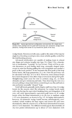
FIGURE 4-4 Typical geometrical confi guration and position (for single level
bonds) of the pulling hook for gold ball bond (top) and ultrasonic wedge bond
(bottom). Pulling hook tends to slip toward the peak of the loop.
wedge bonds. However, in both cases, a pull in the center of the loop for
single-level bonding would provide a more reliable quality control for
the total bonding process.
Advanced autobonders are capable of making loops in almost
any shape and extreme lengths (see App. 9A, Chap. 9 for a descrip-
tion of autobonder “Looping” by Lee Levine). There will be no spe-
cial discussion on pull testing such long, unusually shaped loops,
except to note that during pulling the wire straightens and reaches a
peak at the hook position. If one measures the final peak of the loop
before break, (the loop parameters, H, ε, etc.) then the pull force can
be calculated with Eqs. (4-1) to (4-3). However, some unusual loops
have been designed to miss other chips or structures along their path.
Straightening could cause the wire to contract, snag, etc., on those
obstacles and give erroneous pull data. Thus observing the wire on a
slowed pulling is important before committing to use the pull test on
any particular unusually “shaped” loop.
Gold ball bonds generally yield a higher pull force than Al wedge
bonds for the reasons cited. But ultrasonic Au wedge bonds made
with wire having the equivalent breaking force and elongation of Al
wire will yield approximately equivalent pull forces to Al wedge
bonds when the bond deformation is in the low to medium range
(∼1.5 wire diameters), as shown in Fig. 4-5. At higher deformations,
however, Al ultrasonic wedge bonds become metallurgically over-
worked, which weakens the heel region and lowers the pull force
dramatically, often by a factor of 2, as the bond deformation increases
above 2 wire diameters. The different metallurgical characteristics of
Au wire permit deformations up to about 2.5 wire diameters with