
Page 144 - Mechanical Behavior of Materials
P. 144
Section 4.5 True Stress–Strain Interpretation of Tension Test 145
2
πd /4 d i
˜ ε = ln i = 2ln (4.20)
2
πd /4 d
It should be remembered that Eqs. 4.17 through 4.20 depend on the constant volume assumption and
may be inaccurate unless the inelastic (plastic plus creep) strain is large compared with the elastic
strain.
True strains from Eq. 4.15 are somewhat smaller than the corresponding engineering strains.
But once necking starts and Eq. 4.19 is employed with the rapidly decreasing values of A, the true
strain may increase substantially beyond the engineering strain, as seen in Fig. 4.18.
4.5.3 Limitations on True Stress–Strain Equations
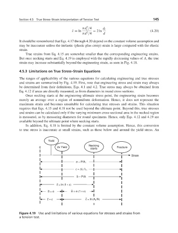
The ranges of applicability of the various equations for calculating engineering and true stresses
and strains are summarized by Fig. 4.19. First, note that engineering stress and strain may always
be determined from their definitions, Eqs. 4.1 and 4.2. True stress may always be obtained from
Eq. 4.12 if areas are directly measured, as from diameters in round cross sections.
Once necking starts at the engineering ultimate stress point, the engineering strain becomes
merely an average over a region of nonuniform deformation. Hence, it does not represent the
maximum strain and becomes unsuitable for calculating true stresses and strains. This situation
requires that Eqs. 4.15 and 4.18 not be used beyond the ultimate point. Beyond this, true stresses
and strains can be calculated only if the varying minimum cross-sectional area in the necked region
is measured, as by measuring diameters for round specimens. Hence, only Eqs. 4.12 and 4.19 are
available beyond the ultimate point where necking starts.
In addition, Eq. 4.18 is limited by the constant volume assumption. Hence, this conversion
to true stress is inaccurate at small strains, such as those below and around the yield stress. An
Yield
Necking
0 2x Yield Fracture
starts
Strain
σ = P/A i
ε = ΔL/L i
~
σ = P/A
~
ε = ln(1 + ε)
~ ~
σ = σ
σ = σ (1 + ε)
~ ε = ε ~ ε = ln(A i /A)
Figure 4.19 Use and limitations of various equations for stresses and strains from
a tension test.