
Page 230 -
P. 230
9.6 CHAPTER NINE
FINISI lED WATER
SLOW SAND FILTER
STORAGE
SOURCE WATER
~7 HEAD SPACE VENT
R
SUPEBNATANT WATFR
V/
SUPERNATANI
WATER DRAIN SCHMUTZDECKE
-.~-, ~
J ,
SAND MED~
FIt TER .TO m WASTE
SUPPORT GRAVEl.
FlOW METER
BACKFILLING
~-~, ~
UlIIIIIIIIIIIIIIIIIIIIIIIIIIIIIIIIIIIII~
LJNI)LI¢IlltAIN
ro
I)lSrRINllllON
I;I
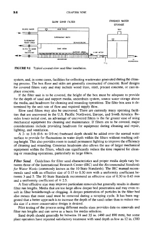
FIGURE 9.1 Typical covered slow sand filter installation.
system, and, in some cases, facilities for collecting wastewater generated during the clean-
ing process. The box floor and sides are generally constructed of concrete. Roof designs
for covered filters vary and may include wood truss, steel, precast concrete, or cast-in-
place concrete.
If the filter unit is to be covered, the height of the box must be adequate to provide
for the depth of sand and support media, underdrain system, source water storage above
the media, and headroom for cleaning and resanding operations. The filter box area is de-
termined by the unit rate of flow and required supply flow.
Slow sand filters may also be uncovered. There are currently many operating facili-
ties that are uncovered in the U.S. Pacific Northwest, Europe, and South America. Be-
sides lower initial cost, an advantage of uncovered filters is the far greater ease of using
mechanical equipment for cleaning and maintenance. If filters are to be covered, major
considerations include providing headroom for equipment during cleaning and repair,
lighting, and ventilation.
A 2- to 3-ft (0.6- to 0.9-m) freeboard depth should be added over the normal water
surface to provide for fluctuations in water depth within the filters without reaching ceil-
ing height. This also provides room to install permanent lighting to improve the efficiency
of cleaning and resanding. Generous headroom also allows the use of larger mechanical
equipment within the filters, which can significantly reduce the time required for clean-
ing or resanding operations, particularly in large filters.
Filter Sand. Guidelines for filter sand characteristics and proper media depth vary be-
tween those of the International Research Center (IRC) and the Recommended Standards
for Water Works (commonly known as the l0 State Standards). The IRC manual recom-
mends sand with an effective size of 0.15 to 0.30 mm with a uniformity coefficient be-
tween 3 and 5. The 10 State Standards recommend an effective size of 0.30 to 0.45 mm
and a uniformity coefficient of <- 2.5.
A finer effective size may improve particulate removals but generally results in shorter
filter run lengths. Media that are too large allow deeper bed penetration and may even re-
sult in filter breakthrough or clogging. A deeper penetration of particles in the filter bed
also means that more sand must be removed during a scraping cycle. It has been sug-
gested that a better approach is to increase the depth of the sand rather than to reduce me-
dia size if a more conservative design is desired.
Pilot testing of the process using different media sizes provides data on removals and
filter run lengths and can serve as a basis for media selection.
Sand depth should generally be between 18 and 35 in. (460 and 890 mm), but some
plant operators have reported satisfactory treatment with sand depth as low as 12 in. (300