
Page 235 -
P. 235
SLOW SAND AND DIATOMACEOUS EARTH FILTRATION 9.11
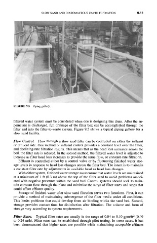
FIGURE 9.5 Piping gallery.
filtered water system must be considered when one is designing this drain. After the su-
pernatant is discharged, full drainage of the filter box can be accomplished through the
filter and into the filter-to-waste system. Figure 9.5 shows a typical piping gallery for a
slow sand facility.
Flow Control. Flow through a slow sand filter can be controlled on either the influent
or effluent side. One method of influent control provides a constant level over the filter,
and declining-rate filtration results. This means that as the head loss increases across the
bed, the filter rate is reduced. In the second method, the filtered water level is adjusted to
increase as filter head loss increases to provide the same flow, or constant-rate filtration.
Effluent is controlled either by a control valve or by fluctuating finished water stor-
age levels in response to head loss changes across the filter bed. The intent is to maintain
a constant filter rate by adjustments in available head as head loss changes.
With either system, finished water storage must ensure that water levels are maintained
at a minimum of 1 ft (0.3 m) above the top of the filter sand to avoid problems associ-
ated with negative pressures within the sand bed. Control systems should seek to main-
tain constant flow through the plant and minimize the surge of filter starts and stops that
could affect effluent quality.
Storage of finished water after slow sand filtration serves two functions. First, it can
provide a method of maintaining submergence of the filter media under all conditions.
This limits problems that could develop fi'om air binding within the sand bed. Second,
storage provides contact time for disinfection after filtration. The volume and form of
storage vary according to system requirements.
Filter Rates. Typical filter rates are usually in the range of 0.04 to 0.10 gpm/ft 2 (0.09
to 0.24 m/h). Filter rates can be established through pilot testing. In some cases, it has
been demonstrated that higher rates are possible while maintaining acceptable effluent