
Page 233 -
P. 233
SLOW SAND AND DIATOMACEOUS EARTH FILTRATION 9.9
TO DISTRIBUTION
SYSTEM
I
.RCM
CONTROL
RESERVOIR
BUILDING
, ~RED
t WAI~R
PIFING GALLERY
FILTER F[ LTER FILTER FILTER
NO. 1 NO. 2 NO. ,3 NO. 4
ENTRANCE ENTRANCE
STRUCTURE STRUCTURE
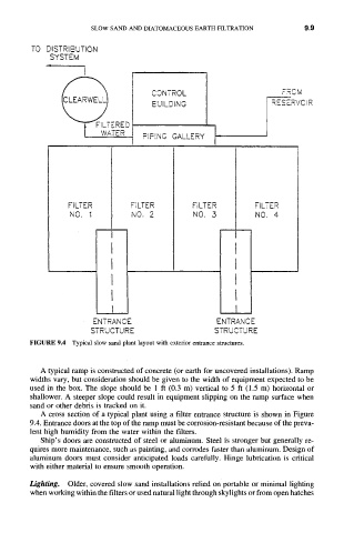
FIGURE 9.4 Typical slow sand plant layout with exterior entrance structures.
A typical ramp is constructed of concrete (or earth for uncovered installations). Ramp
widths vary, but consideration should be given to the width of equipment expected to be
used in the box. The slope should be 1 ft (0.3 m) vertical to 5 ft (1.5 m) horizontal or
shallower. A steeper slope could result in equipment slipping on the ramp surface when
sand or other debris is tracked on it.
A cross section of a typical plant using a filter entrance structure is shown in Figure
9.4. Entrance doors at the top of the ramp must be corrosion-resistant because of the preva-
lent high humidity from the water within the filters.
Ship's doors are constructed of steel or aluminum. Steel is stronger but generally re-
quires more maintenance, such as painting, and corrodes faster than aluminum. Design of
aluminum doors must consider anticipated loads carefully. Hinge lubrication is critical
with either material to ensure smooth operation.
Lighting. Older, covered slow sand installations relied on portable or minimal lighting
when working within the filters or used natural light through skylights or from open hatches