
Page 232 -
P. 232
9.8 CHAPTER NINE
sand, and the fine layer prevents sand from migrating down to clog underdrain openings.
The 10-State Standards recommend gravel support layers similar to those required for a
rapid sand installation with a media depth between 18 and 24 in. (460 and 610 mm) and
gravel sizes in a range from 3A2 to 2 l& in. (2 to 64 mm) in a five-layer system.
Source Water Storage. Source water storage is the depth and volume of water overly-
ing the sand surface within the basin. This volume varies in different designs (between 3
and 24 h of plant capacity). As storage capacity increases, there are some benefits with
respect to equalizing source water quality, sedimentation of larger particles, and even bi-
ological action within the water column itself.
The primary purpose of the water level above the sand, however, is to provide the
driving head across the filter bed. A typical terminal head loss for a slow sand filter is in
the range of 4 to 5 ft (1.2 to 1.5 m). Therefore typical depths of water above the sand
should range between 6 and 7 ft (1.8 and 2.1 m) to provide for the additional driving force
required for head loss through the clean sand bed and through the piping systems. If a fil-
ter is to be covered, the height of the filter box above the sand is governed primarily
by space requirements for cleaning and resanding, so provision of a 6- to 7-ft (1.8- to
2. l-m) depth of water can easily be accomplished.
Access for Cleaning and Maintenance. Early sand filters were constructed either with
no covers (roofs) or with earthen embankments over cast-in-place concrete roofing sys-
tems. Filters constructed with a roof typically used access hatches or ports spaced at in-
tervals above the bed surface. Cleaning the beds was cumbersome and normally accom-
plished either by manually hoisting the scraped schmutzdecke up through the access way
or by hydraulic transfer of a slurry of removed material through a piping system.
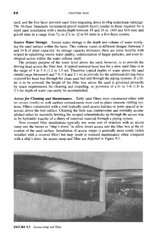
New covered filter installations typically use some sort of structure with an access
ramp into the basins or "ship's doors" to allow direct access into the filter box at the el-
evation of the sand surface. Installation of access ramps is generally more costly (when
installed with a covered filter) but may result in reduced maintenance when compared
with a ship's door. An access ramp and filter are depicted in Figure 9.3.
FIGURE 9.3 Access ramp and filter.