
Page 231 -
P. 231
SLOW SAND AND DIATOMACEOUS EARTH FILTRATION 9.7
mm). Most slow sand plants in the United States are designed with a minimum sand depth
of 30 in. (760 mm).
If filters are cleaned by manual scraping, about 1,5 in. (1 cm) of sand is removed dur-
ing the scraping. Final sand depth should be determined based on cleaning method, an-
ticipated filter run lengths, number of scrapings desired before resanding, sand availabil-
ity and expense, and impact of downtimes on plant capacity. The minimum depth before
resanding should be 18 in. (460 mm).
Underdrain and Support System. One common type of underdrain consists of a mani-
fold and perforated laterals installed below the sand bed. Most new designs use a plastic
piping system for filter underdrains. Piping material must be certified for contact with
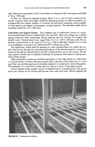
potable water. Typical lateral sizes range from 4 to 8 in. (100 to 200 mm) with the un-
derdrain system header in the range of 8 to 16 in. (200 to 400 mm). Figure 9.2 is a view
of an installation in progress of a perforated PVC underdrain system.
The underdrain system must be designed to cause minimal head loss within the sys-
tem. Head losses through the individual perforations of the laterals must be a fraction of
head loss through the lateral itself to provide a balanced flow across the system. The de-
sign engineer should refer to hydraulic textbooks for guidance with respect to piping man-
ifold system designs.
Other underdrain systems use prefabricated plastic or clay filter blocks or a false floor
of concrete blocks or brick with gravel media above. Because of the large area of a slow
sand filter, the prefabricated type is normally expensive to install and is used infrequently.
The hydraulics of a false floor system must be similar to those of the piped system.
Gravel support media usually consist of multiple layers of graded gravel. The gravel
layers are coarsest on the bottom and become finer with each layer. Gravel supports the
FIGURE 9.2 Underdrain installation.