
Page 249 -
P. 249
SLOW SAND AND DIATOMACEOUS EARTH FILTRATION 9.25
= Control Valve
Body Feed Precoat
Raw
Water
Filter Outlet ~
Product
(~Drain to Waste
Water
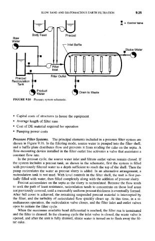
FIGURE 9.16 Pressure system schematic.
• Capital costs of structures to house the equipment
• Average length of filter runs
• Cost of DE material required for operation
• Pumping power costs
Pressure Filter Systems. The principal elements included in a pressure filter system are
shown in Figure 9.16. In the filtering mode, source water is pumped into the filter shell,
and a baffle plate distributes flow and prevents it from eroding the cake on the septa. A
flow-measuring device installed in the filter outlet line activates a valve that maintains a
constant flow rate.
In the precoat cycle, the source water inlet and filtrate outlet valves remain closed. If
the system includes a precoat tank, as shown in the schematic, first the system is filled
with previously filtered water to a depth sufficient to reach the top of the shell. Then the
pump recirculates the water as precoat slurry is added. In an alternative arrangement, a
recirculation tank is not used. With level controls in the filter shell, the unit is first par-
tially filled with water, then filled completely along with the addition of precoat slurry.
Precoat accumulates on the septa as the slurry is recirculated. Because the flow tends
to seek the path of least resistance, recirculation tends to concentrate on those leaf areas
not previously covered, until a reasonably uniform precoat thickness is eventually formed.
After full cover is achieved, the remaining suspended precoat material is intercepted by
the filter, and the turbidity of recirculated flow quickly clears up. At this time, in a si-
multaneous operation, the recirculation valve closes, and the filter inlet and outlet valves
open to initiate the filter cycle.
When the maximum available head differential is reached, the filter run is terminated
and the filter is cleaned. In the cleaning cycle the inlet valve is closed, the waste valve is
opened, and after the unit is fully drained, sluice water is turned on to flush away the fil-
ter cake.