
Page 122 - 15 Dangerously Mad Projects for the Evil Genius
P. 122
Chapter 8 ■ Persistence-of-Vision Display 101
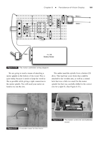
Figure 8-30 The motor controller wiring diagram
We are going to need a means of attaching a The author used the spindle from a broken CD
motor spindle to the bottom of the wood. This is drive. This had four screw holes that could be
quite tricky because it needs to keep the wood as attached to the wooden arm, as well as a central
flat as possible while giving a tight connection to hole that was a little too small for the motor
the motor spindle. You will need your motor on spindle but that was carefully drilled to the correct
hand to try out the size. size for a tight fit. (See Figure 8-33.)
Figure 8-32 The motor controller and batteries
boxed
Figure 8-31 A wooden base for the motor