
Page 118 - 15 Dangerously Mad Projects for the Evil Genius
P. 118
Chapter 8 ■ Persistence-of-Vision Display 97
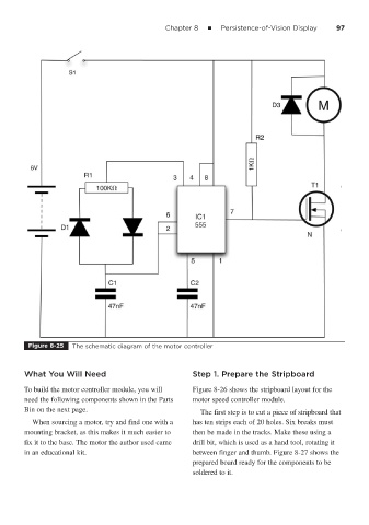
Figure 8-25 The schematic diagram of the motor controller
What You Will Need Step 1. Prepare the Stripboard
To build the motor controller module, you will Figure 8-26 shows the stripboard layout for the
need the following components shown in the Parts motor speed controller module.
Bin on the next page.
The first step is to cut a piece of stripboard that
When sourcing a motor, try and find one with a has ten strips each of 20 holes. Six breaks must
mounting bracket, as this makes it much easier to then be made in the tracks. Make these using a
fix it to the base. The motor the author used came drill bit, which is used as a hand tool, rotating it
in an educational kit. between finger and thumb. Figure 8-27 shows the
prepared board ready for the components to be
soldered to it.