
Page 120 - 15 Dangerously Mad Projects for the Evil Genius
P. 120
Chapter 8 ■ Persistence-of-Vision Display 99
Figure 8-27 The motor controller module stripboard ready for soldering
The three holes for the variable resistor may Step 3. Solder the Remaining
need enlarging with a drill. Components
We can now solder the rest of the components,
Step 2. Solder the Links
starting with those lowest in profile. Solder the IC
Resistor and Diodes
first, and then the capacitors and transistor.
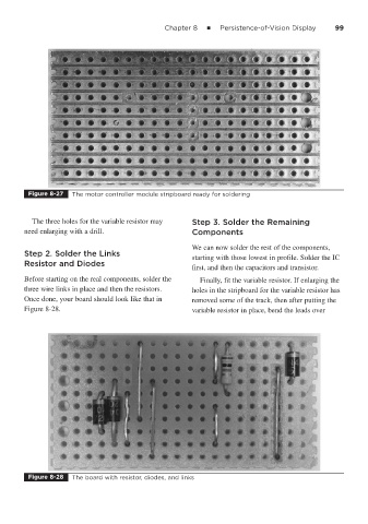
Before starting on the real components, solder the Finally, fit the variable resistor. If enlarging the
three wire links in place and then the resistors. holes in the stripboard for the variable resistor has
Once done, your board should look like that in removed some of the track, then after putting the
Figure 8-28. variable resistor in place, bend the leads over
Figure 8-28 The board with resistor, diodes, and links