
Page 121 - 15 Dangerously Mad Projects for the Evil Genius
P. 121
100 15 Dangerously Mad Projects for the Evil Genius
toward the center of the board so they can be will vibrate when the LED arm is attached, so it is
soldered over a few holes worth of track. a good idea to build a solid base for the project.
We are also going to attach a screw terminal for The base the author used takes this to an
connecting the motor leads. So, solder a pair of extreme and is constructed from reclaimed two-by-
short half-inch (10mm) wires to the appropriate four wood, crudely screwed together (Figure 8-31).
holes (see Figure 8-26). You should find that some The dimensions of this are really not critical at
of the snipped resistor leads should be about the all, as long as the motor can be mounted in such a
right length. way that its spindle is not impeded and there is
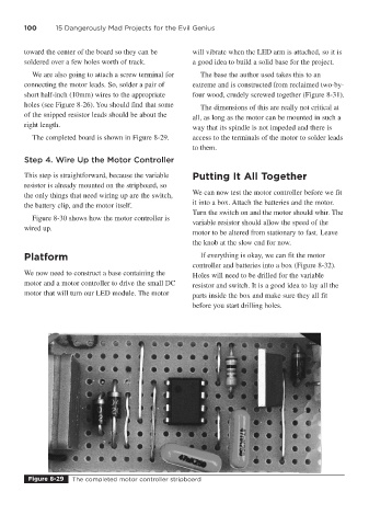
The completed board is shown in Figure 8-29. access to the terminals of the motor to solder leads
to them.
Step 4. Wire Up the Motor Controller
This step is straightforward, because the variable Putting It All Together
resistor is already mounted on the stripboard, so
We can now test the motor controller before we fit
the only things that need wiring up are the switch,
it into a box. Attach the batteries and the motor.
the battery clip, and the motor itself.
Turn the switch on and the motor should whir. The
Figure 8-30 shows how the motor controller is
variable resistor should allow the speed of the
wired up.
motor to be altered from stationary to fast. Leave
the knob at the slow end for now.
Platform If everything is okay, we can fit the motor
controller and batteries into a box (Figure 8-32).
We now need to construct a base containing the Holes will need to be drilled for the variable
motor and a motor controller to drive the small DC resistor and switch. It is a good idea to lay all the
motor that will turn our LED module. The motor parts inside the box and make sure they all fit
before you start drilling holes.
Figure 8-29 The completed motor controller stripboard