
Page 107 - Hybrid Enhanced Oil Recovery Using Smart Waterflooding
P. 107
CHAPTER 4 Hybrid Chemical EOR Using Low-Salinity and Smart Waterflood 99
(A) (B)
0.4 0.4
Equilibrium oil-brine contact angle: Equilibrium oil-brine contact angle:
Swi Swi
HSWF - 1PV LSWF - 1PV
HSWF- Sor LSWF- Sor
0.3 Average oil-brine contact angle: 0.3 Average oil-brine contact angle:
Swi Swi
Relative frequency 0.2 Relative frequency 0.2 LSWF- Sor
HSWF - 1PV
LSWF - 1PV
HSWF- Sor
0.1 0.1
0.0 0.0
60 70 80 90 100 110 120 130 140 150 160 50 60 70 80 90 100 110 120 130 140 150 160
Contact angle (degrees) Contact angle (degrees)
(C) (D)
0.40 0.4
Equilibrium oil-brine contact angle: Equilibrium oil-brine contact angle:
Swi Swi
0.35
HSSWF - 1PV LSSWF - 1PV
HSSWF- Sor LSSWF- Sor
0.30 Average oil-brine contact angle: 0.3 Average oil-brine contact angle:
Swi Swi
Relative frequency 0.20 HSSWF- Sor Relative frequency 0.2
LSSWF - 1PV
HSSWF - 1PV
0.25
LSSWF- Sor
0.15
0.10 0.1
0.05
0.00 0.0
50 60 70 80 90 100 110 120 130 140 150 160 50 60 70 80 90 100 110 120 130 140 150 160
Contact angle (degrees) Contact angle (degrees)
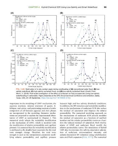
FIG. 4.29 Distribution of in situ contact angle during coreflooding of (A) conventional water flood, (B) low-
salinity waterflood, (C) high-salinity surfactant flood, and (D) low-salinity surfactant flood. (Credit: From
Mirchi, V. (2018). Pore-scale investigation of the effect of surfactant on fluid occupancies during low-salinity
waterflooding in carbonates. Paper presented at the SPE Annual technical Conference and exhibition, Dallas,
Texas, USA, 24e26 September. https://doi.org/10.2118/194045-STU.)
importance in the modeling of LSWF mechanism, the between high and low salinity threshold conditions.
aqueous reactions, mineral reactions of quartz, K- In addition, the IFT reduction and wettability modifica-
feldspar, and calcite, and partitioning reaction of acidic tion in the mechanisms of surfactant EOR also reduce
component of oil between aqueous and oleic phases the residual oil saturation and improve the relative
are incorporated in the modeling. Extensive mecha- permeability. The numerical modeling approach on
nisms are proposed to explain the experimental obser- the mechanisms of surfactant EOR process modifies
vation of LSWF as summarized in Chapter 2. This the residual oil saturation as a function of capillary
numerical study adapts the wettability modification number and the relative permeability curves as a func-
as the mechanism of LSWF, which is modeled with tion the reduced residual oil saturation. Both mecha-
the modification of relative permeability and capillary nisms of LSWF and surfactant flood modify the
pressure. It is assumed that the wettability modification relative permeability curves. The simulation of hybrid
is attributed to the double layer expansion by the total LSSF also incorporates the salinity-dependent adsorp-
ionic strength change. Therefore, the total ionic tion of surfactant, microemulsion viscosity, and
strength is used as the interpolation parameter modi- salinity-dependent IFT reduction using solubilization
fying relative permeability and capillary pressure ratio and Huh’sequation(Huh, 1979). The numerical