
Page 161 - Acquisition and Processing of Marine Seismic Data
P. 161
152 2. MARINE SEISMIC DATA ACQUISITION
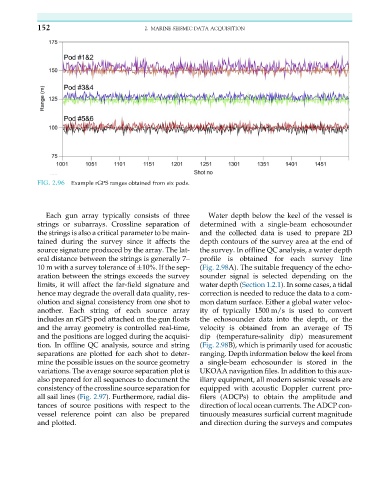
FIG. 2.96 Example rGPS ranges obtained from six pods.
Each gun array typically consists of three Water depth below the keel of the vessel is
strings or subarrays. Crossline separation of determined with a single-beam echosounder
the strings is also a critical parameter to be main- and the collected data is used to prepare 2D
tained during the survey since it affects the depth contours of the survey area at the end of
source signature produced by the array. The lat- the survey. In offline QC analysis, a water depth
eral distance between the strings is generally 7– profile is obtained for each survey line
10 m with a survey tolerance of 10%. If the sep- (Fig. 2.98A). The suitable frequency of the echo-
aration between the strings exceeds the survey sounder signal is selected depending on the
limits, it will affect the far-field signature and water depth (Section 1.2.1). In some cases, a tidal
hence may degrade the overall data quality, res- correction is needed to reduce the data to a com-
olution and signal consistency from one shot to mon datum surface. Either a global water veloc-
another. Each string of each source array ity of typically 1500 m/s is used to convert
includes an rGPS pod attached on the gun floats the echosounder data into the depth, or the
and the array geometry is controlled real-time, velocity is obtained from an average of TS
and the positions are logged during the acquisi- dip (temperature-salinity dip) measurement
tion. In offline QC analysis, source and string (Fig. 2.98B), which is primarily used for acoustic
separations are plotted for each shot to deter- ranging. Depth information below the keel from
mine the possible issues on the source geometry a single-beam echosounder is stored in the
variations. The average source separation plot is UKOAA navigation files. In addition to this aux-
also prepared for all sequences to document the iliary equipment, all modern seismic vessels are
consistency of the crossline source separation for equipped with acoustic Doppler current pro-
all sail lines (Fig. 2.97). Furthermore, radial dis- filers (ADCPs) to obtain the amplitude and
tances of source positions with respect to the direction of local ocean currents. The ADCP con-
vessel reference point can also be prepared tinuously measures surficial current magnitude
and plotted. and direction during the surveys and computes