
Page 172 - Acquisition and Processing of Marine Seismic Data
P. 172
2.6 QC IN DATA ACQUISITION 163
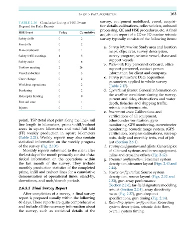
TABLE 2.20 Cumulative Listing of HSE Events survey, equipment mobilized, vessel, acquisi-
Prepared for Daily Reports tion details, calibrations, collected data, onboard
processing, QC and HSE procedures, etc. A final
acquisition report of a 2D or 3D marine seismic
HSE Event Today Cumulative
Safety drills 0 2 survey typically consists of the following items:
Fire drills 0 2
a. Survey information: Study area and location
Man overboard 0 1
maps, objectives, survey description,
Safety/HSE meetings 1 5 survey program, seismic vessel, chase and
support vessels.
Safety audit 0 6
b. Personnel: Key personnel onboard, office
Toolbox meeting 2 26
support personnel, contact person
Vessel induction 0 3 information for client and company.
c. Survey parameters: Data acquisition
Crew change 0 2
parameters applied to whole survey
Workboat operations 0 2
(Table 2.17).
Bunkering 0 2 d. Operational factors: General information on
the weather conditions during the survey,
Helicopter landing 0 0
current and tides, obstructions and water
First aid case 0 1
depth, fisheries and shipping traffic,
Injures 0 1 seismic interference, etc.
e. Instrument tests: Calibrations and
verifications of all equipment,
point), TSP (total shot point along the line), sail echosounder verification, gyro
line length in kilometers, prime/infill/reshoot monitoring, GPS monitoring, currentmeter
areas in square kilometers and total full fold monitoring, acoustic range system, rGPS
(FF) weekly production in square kilometers verification, compass calibrations, start-up
(Table 2.21). Weekly reports may also contain tests, daily and monthly tests, end of job
statistical information on the weekly progress test (Section 2.6.1).
of the survey (Fig. 2.106). f. Towing configuration and offsets: General plot
Monthly reports submitted to the client after of all towed systems and in-sea equipment,
the last day of the month primarily consist of sta- inline and crossline offsets (Fig. 2.42).
tistical information on the operations within g. Streamer configuration: Streamer system
the last month of the survey. They include description, streamer layout (Figs. 2.43 and
monthly production statistics of the completed 2.44).
prime, infill and reshoot lines for a cumulative h. Source configuration: Source system
demonstration of operational times, stand-by, description, source layout (Figs. 2.32 and
downtimes, and mob/demob periods. 2.33), gun array performance
(Section 2.2.6), far-field signature modeling
2.6.5.5 Final Survey Report results (Section 2.2.4), array directivity
After completion of a survey, a final survey maps (Fig. 2.37), gun drop-out
report is prepared usually within the following specifications, gun timing (Fig. 2.14).
60 days. These reports are quite comprehensive i. Recording system configuration: Recording
and include all the necessary information about system description, seismic data flow,
the survey, such as statistical details of the overall system timing.