
Page 207 - Acquisition and Processing of Marine Seismic Data
P. 207
198 3. NOISE IN MARINE SEISMICS
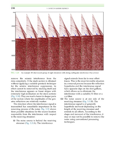
FIG. 3.28 An example 3D shot record group of eight streamers with strong earthquake interference (blue arrows).
remove the seismic interference from the signal extends from far to near offset
data completely. If the stack section is obtained traces. This is the most favorable situation
without applying a suitable prestack technique in a removal process because the reflection
for the seismic interference suppression, its hyperbolas and the interference signal
effect cannot be removed by stacking itself and have opposite dips on the shot gathers,
the interference appears as linear stripes with which allows us to eliminate the
extremely high inclination on the stack sections interference with a suitable f-k filter or a
(Fig. 3.30). They are much clearer in deeper parts τ-p filter.
of the section where the amplitudes of the gen- (ii) The noise source is at one side of the
uine reflections are relatively weaker. receiving streamer (Fig. 3.31B). The
The direction where the interference signal is interference signal is of generally
transmitted has remarkable importance in the hyperbolic moveout depending on the
removing process of the noise. Fig. 3.31 shows length of the receiving streamer and
three possible situations for the source location extends to all offsets. According to the
responsible from the interference with respect shape and moveout of the interference, it
to the receiving streamer: may or may not be possible to remove the
noise using conventional processing
(i) The noise source is behind the receiving
streamer (Fig. 3.31A). The interference techniques.