
Page 448 - Acquisition and Processing of Marine Seismic Data
P. 448
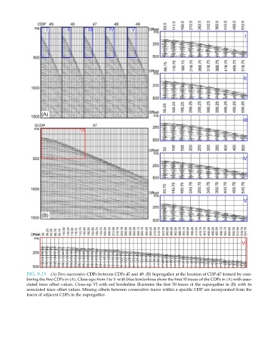
FIG. 9.13  (A) Five successive CDPs between CDPs 45 and 49. (B) Supergather at the location of CDP-47 formed by com-
           bining the five CDPs in (A). Close-ups from I to V with blue borderlines show the first 10 traces of the CDPs in (A) with asso-
           ciated trace offset values. Close-up VI with red borderline illustrates the first 50 traces of the supergather in (B) with its
           associated trace offset values. Missing offsets between consecutive traces within a specific CDP are incorporated from the
           traces of adjacent CDPs in the supergather.