
Page 453 - Acquisition and Processing of Marine Seismic Data
P. 453
444 9. VELOCITY ANALYSIS
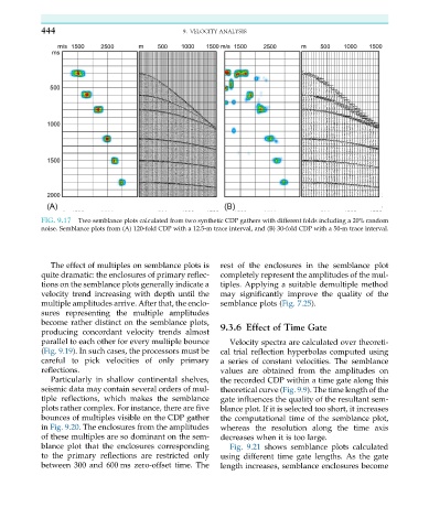
FIG. 9.17 Two semblance plots calculated from two synthetic CDP gathers with different folds including a 20% random
noise. Semblance plots from (A) 120-fold CDP with a 12.5-m trace interval, and (B) 30-fold CDP with a 50-m trace interval.
The effect of multiples on semblance plots is rest of the enclosures in the semblance plot
quite dramatic: the enclosures of primary reflec- completely represent the amplitudes of the mul-
tions on the semblance plots generally indicate a tiples. Applying a suitable demultiple method
velocity trend increasing with depth until the may significantly improve the quality of the
multiple amplitudes arrive. After that, the enclo- semblance plots (Fig. 7.25).
sures representing the multiple amplitudes
become rather distinct on the semblance plots, 9.3.6 Effect of Time Gate
producing concordant velocity trends almost
parallel to each other for every multiple bounce Velocity spectra are calculated over theoreti-
(Fig. 9.19). In such cases, the processors must be cal trial reflection hyperbolas computed using
careful to pick velocities of only primary a series of constant velocities. The semblance
reflections. values are obtained from the amplitudes on
Particularly in shallow continental shelves, the recorded CDP within a time gate along this
seismic data may contain several orders of mul- theoretical curve (Fig. 9.9). The time length of the
tiple reflections, which makes the semblance gate influences the quality of the resultant sem-
plots rather complex. For instance, there are five blance plot. If it is selected too short, it increases
bounces of multiples visible on the CDP gather the computational time of the semblance plot,
in Fig. 9.20. The enclosures from the amplitudes whereas the resolution along the time axis
of these multiples are so dominant on the sem- decreases when it is too large.
blance plot that the enclosures corresponding Fig. 9.21 shows semblance plots calculated
to the primary reflections are restricted only using different time gate lengths. As the gate
between 300 and 600 ms zero-offset time. The length increases, semblance enclosures become