
Page 76 - Adaptive Identification and Control of Uncertain Systems with Nonsmooth Dynamics
P. 76
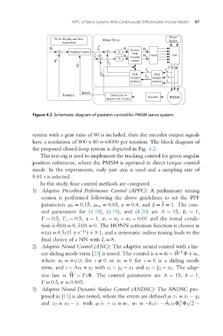
APPC of Servo Systems With Continuously Differentiable Friction Model  67


                            Figure 4.2 Schematic diagram of position control for PMSM servo system.


                            system with a gear ratio of 80 is included, then the encoder output signals
                            have a resolution of 800 × 80 = 64000 per rotation. The block diagram of
                            the proposed closed-loop system is depicted in Fig. 4.2.
                               This test-rig is used to implement the tracking control for given angular
                            position references, where the PMSM is operated in direct torque control
                            mode. In the experiments, only yaw axis is used and a sampling rate of
                            0.01 s is selected.
                               In this study, four control methods are compared:
                            1) Adaptive Prescribed Performance Control (APPC): A preliminary tuning
                               session is performed following the above guidelines to set the PPF
                               parameters μ 0 = 0.15, μ ∞ = 0.03, κ = 0.4, and δ = δ = 1. The con-
                                                                              ¯
                               trol parameters for (4.18), (4.19), and (4.20)are
 = 15, k 1 = 1,
                                 = 0.5,   a = 0.5, η = 1, σ 1 = σ 2 = σ 3 = 0.01 and the initial condi-
                                     θ(0) = 0, ˆε(0) = 0. The HONN activation function is chosen as
                               tion is ˆ
                               σ(x) = 0.5/(1 + e −1x ) + 0.1, and a systematic online tuning leads to the
                               final choice of a NN with L = 8.
                            2) Adaptive Neural Control (ANC): The adaptive neural control with a lin-
                                                                                     T
                               ear sliding mode term [23]istested. Thecontrolis u = ks + ˆ W   +u 1,
                               where u 1 = σs/|s| for s
= 0or u 1 = 0for s = 0 is a sliding mode
                               term, and s =
e 1 + e 2 with e 1 = y d − x 1 and e 2 =˙y d − x 2. The adap-
                                           ˙
                                           ˆ
                               tive law is W =  s . The control parameters are
 = 15, k = 1,
                                 = 0.5,σ = 0.005.
                            3) Adaptive Neural Dynamic Surface Control (ANDSC):The ANDSCpro-
                               posed in [11] is also tested, where the errors are defined as z 1 = x 1 − y d
                                                                                     T
                                                       s
                                                                                ˆ
                               and z 2 = x 2 − s 1 with μ 1 ˙ 1 + s 1 = α 1, α 1 =−k 1z 1 − θ 1z 1     1 /2 −
                                                                                     1