
Page 122 - Advanced Gas Turbine Cycles
P. 122
94 Advanced gas turbine cycles
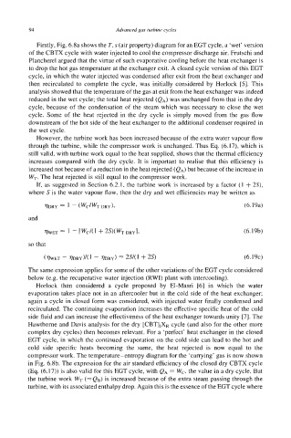
Firstly, Fig. 6.8a shows the T, s (air property) diagram for an EGT cycle, a ‘wet’ version
of the CBTX cycle with water injected to cool the compressor discharge air. Frutschi and
Plancherel argued that the virtue of such evaporative cooling before the heat exchanger is
to drop the hot gas temperature at the exchanger exit. A closed cycle version of this EGT
cycle, in which the water injected was condensed after exit from the heat exchanger and
then recirculated to complete the cycle, was initially considered by Horlock [5]. This
analysis showed that the temperature of the gas at exit from the heat exchanger was indeed
reduced in the wet cycle; the total heat rejected (QA) was unchanged from that in the dry
cycle, because of the condensation of the steam which was necessary to close the wet
cycle. Some of the heat rejected in the dry cycle is simply moved from the gas flow
downstream of the hot side of the heat exchanger to the additional condenser required in
the wet cycle.
However, the turbine work has been increased because of the extra water vapour flow
through the turbine, while the compressor work is unchanged. Thus Eq. (6.17), which is
still valid, with turbine work equal to the heat supplied, shows that the thermal efficiency
increases compared with the dry cycle. It is important to realise that this efficiency is
increased not because of a reduction in the heat rejected (QA) but because of the increase in
WT. The heat rejected is still equal to the compressor work.
If, as suggested in Section 6.2.1, the turbine work is increased by a factor (1 + 29,
where S is the water vapour flow, then the dry and wet efficiencies may be written as
WRY = 1 - (WC/WT DRY), (6.19a)
and
%ET = - [wC/(I f 2S)(WT DRY], (6.19b)
so that
(WET - TDRY)~~ - WRY) 2W1 + 2s) (6.19~)
The same expression applies for some of the other variations of the EGT cycle considered
below (e.g. the recuperative water injection (RWI) plant with intercooling).
Horlock then considered a cycle proposed by El-Masri [6] in which the water
evaporation takes place not in an aftercooler but in the cold side of the heat exchanger;
again a cycle in closed form was considered, with injected water finally condensed and
recirculated. The continuing evaporation increases the effective specific heat of the cold
side fluid and can increase the effectiveness of the heat exchanger towards unity [7]. The
Hawthorne and Davis analysis for the dry [CBTIIXR cycle (and also for the other more
complex dry cycles) then becomes relevant. For a ‘perfect’ heat exchanger in the closed
EGT cycle, in which the continued evaporation on the cold side can lead to the hot and
cold side specific heats becoming the same, the heat rejected is now equal to the
compressor work. The temperature-entropy diagram for the ‘carrying’ gas is now shown
in Fig. 6.8b. The expression for the air standard efficiency of the closed dry CBTX cycle
(Eq. (6.17)) is also valid for this EGT cycle, with QA = WC, the value in a dry cycle. But
the turbine work WT (= QB) is increased because of the extra steam passing through the
turbine, with its associated enthalpy drop. Again this is the essence of the EGT cycle where