Page 123 - Advanced Gas Turbine Cycles
P. 123

Chapter 6. ‘Wet’ gas turbine plants           95


                        T


                                                          S


                            I
                                                         S


                                                     3/
                        T


                                                       s
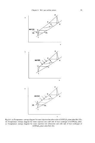
      Fig. 6.8. (a) Temperature-entropy diagram for water injection into aftercooler of [CHTIIXR plant (after Ref. 151).
      (b) Temperature-entropy  diagram for  water injection  into  cold  side of heat exchanger of  [CHTllXR plant.
      (c) Temperature-entropy  diagram  for  water  injection  into aftercooler and  cold  side  of  heat  exchanger of
                                [cHT]&  plant (after Ref. [5]).
   118   119   120   121   122   123   124   125   126   127   128