
Page 181 - Advanced Gas Turbine Cycles
P. 181
Chapter 8. Novel gas turbine cycles I47
the scrubbing process to intercool and aftercool the compression in the gas turbine
cycle can restore about half the loss in thermal efficiency. After a very careful
optimisation, and by including amine regeneration, Corti and Manfrida estimated the
cost of electricity generated by this plant, including COz disposal, to be about 4.7 c/
kWh. This is slightly less than the estimate of Chiesa and Consonni who based their
calculations on different sources.
Fig. 8.8 shows yet another example (Cycle A3) of the use of the semi-closed cycle
concept, suggested by Manfrida [4], in which a recuperative CBTX plant is modified. Now
the exhaust gas from the gas turbine is cooled in a heat exchanger (rather than the HRSG of
a CCGT plant). It then enters the chemical absorption plant where some C02 is
sequestrated and liquefied before disposal. The remainder of the exhaust gas is recirculated
into compressor inlet after additional cooling. Manfrida finds slightly lower efficiency in
the plant A3 compared with plant A2, but argues that it may prove simpler and more
economic than the semi-closed IGCC plant.
8.6.2. Cycles B with modijication of the fuel in combustion through thermo-chemical
recuperation [TCR]
We consider next the cycles B of Table 8.1B and the associated Figs. 8.9-8.12; these
cycles involve modification of the fuel used in the combustion process by TCR. There are
two basic types of chemically recuperated gas turbine (CRGT) cycle:
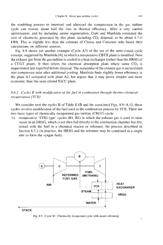
(i) recuperative ‘STIG type’ cycles (Bl, B2) in which the exhaust gas is used to raise
steam in an HRSG, which is not then fed directly to the combustion chamber but first
mixed with the fuel in a chemical reactor or reformer, the process described in
Section 8.5.2 (in practice, the HRSG and the reformer may be combined in a single
unit to form the syngas fuel);
FUEL \
I (METHANE)
AIR FUELGAS HEAT
1 EXCHANGER
I
HRSG
- WATER
STACK
Fig. 8.9. Cycle B1. Chemically recuperated cycle with steam reforming.