
Page 293 - Advanced Organic Chemistry Part A - Structure and Mechanisms, 5th ed (2007) - Carey _ Sundberg
P. 293
274 that exist along the reaction pathway. The sequence of reaction steps and interme-
diates involved in the overall transformation is the reaction mechanism. Reactants,
CHAPTER 3 intermediates, and products correspond to energy minima on the energy diagram and
Structural Effects on are separated by activated complexes or transition states, which are the molecular
Stability and Reactivity
arrangements having the maximum energy for each successive step of the reaction
mechanism. Figure 3.2 gives reaction energy diagrams for hypothetical reactions that
proceed in one, two, or three steps through zero, one, or two intermediates. For the
example in Figure 3.2. these are:
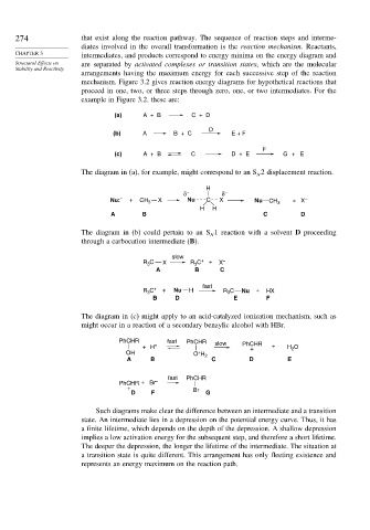
(a) A + B C + D
D
(b) A B + C E + F
F
(c) A + B C D + E G + E
The diagram in (a), for example, might correspond to an S 2 displacement reaction.
N
H
δ − δ −
Nu: – + CH 3 X Nu C X Nu CH 3 + X –
H H
A B C D
The diagram in (b) could pertain to an S 1 reaction with a solvent D proceeding
N
through a carbocation intermediate (B).
slow
R C X R C + + X –
3
3
A B C
fast
R C + + Nu H R 3 C Nu + HX
3
B D E F
The diagram in (c) might apply to an acid-catalyzed ionization mechanism, such as
might occur in a reaction of a secondary benzylic alcohol with HBr.
PhCHR fast PhCHR slow PhCHR
+ H + + + H O
2
+
OH O H 2
A B C D E
fast PhCHR
PhCHR + Br –
+ Br
D F G
Such diagrams make clear the difference between an intermediate and a transition
state. An intermediate lies in a depression on the potential energy curve. Thus, it has
a finite lifetime, which depends on the depth of the depression. A shallow depression
implies a low activation energy for the subsequent step, and therefore a short lifetime.
The deeper the depression, the longer the lifetime of the intermediate. The situation at
a transition state is quite different. This arrangement has only fleeting existence and
represents an energy maximum on the reaction path.