
Page 449 - Advanced thermodynamics for engineers
P. 449
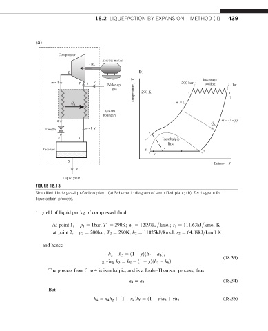
18.2 LIQUEFACTION BY EXPANSION – METHOD (II)          439


               (a)

                         Compressor
                                          Electric motor
                                     - W in
                            2                           (b)
                                                       T                           Interstage
                      m = 1      7  1  y    Make-up                       200 bar  cooling    1 bar
                                                       Temperature,   290 K  2               1 7
                                               gas
                              Q                                         m = 1
                               A
                                           System
                                          boundary
                        3                                                                 m = (1- y)
                                                                                      Q
                   Throttle        m  = 1 - y
                                                             3
                        4        6                                Isenthalpic
                                                                     line
                  Receiver                                 5       4               6
                                                               y
                            5                                                          Entropy , S
                                y
                          Liquid yield
               FIGURE 18.13
               Simplified Linde gas-liquefaction plant. (a) Schematic diagram of simplified plant; (b) T-s diagram for
               liquefaction process.

               1. yield of liquid per kg of compressed fluid


                      At point 1;  p 1 ¼ 1bar; T 1 ¼ 290K; h 1 ¼ 12097kJ kmol; s 1 ¼ 111:63kJ kmol K
                      at point 2;  p 2 ¼ 200bar; T 2 ¼ 290K; h 2 ¼ 11025kJ kmol; s 2 ¼ 64:09kJ kmol K


                  and hence
                                             h 2   h 3 ¼ð1   yÞðh 7   h 6 Þ;
                                                                                           (18.33)
                                          giving h 3 ¼ h 2  ð1   yÞðh 7   h 6 Þ
                     The process from 3 to 4 is isenthalpic, and is a Joule–Thomson process, thus

                                                     h 4 ¼ h 3                             (18.34)
                     But

                                       h 4 ¼ x 4 h g þð1   x 4 Þh f ¼ð1   yÞh 6 þ yh 5     (18.35)