
Page 448 - Advanced thermodynamics for engineers
P. 448
438 CHAPTER 18 LIQUEFACTION OF GASES
3000
Vapour region
Specific enthalpy / kJ/kg 2000 Liquid + vapour region point
Critical
1000
0 Liquid region
1 10 100 1000
Pressure / bar
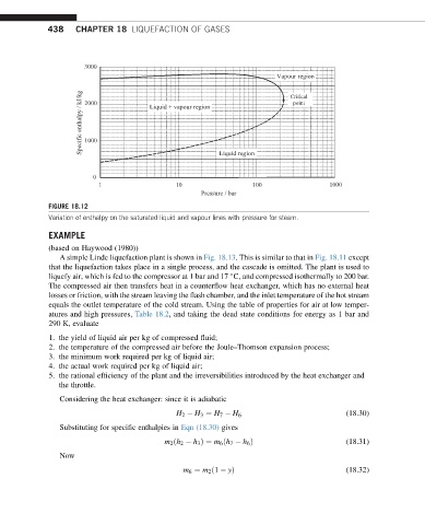
FIGURE 18.12
Variation of enthalpy on the saturated liquid and vapour lines with pressure for steam.
EXAMPLE
(based on Haywood (1980))
A simple Linde liquefaction plant is shown in Fig. 18.13. This is similar to that in Fig. 18.11 except
that the liquefaction takes place in a single process, and the cascade is omitted. The plant is used to
liquefy air, which is fed to the compressor at 1 bar and 17 C, and compressed isothermally to 200 bar.
The compressed air then transfers heat in a counterflow heat exchanger, which has no external heat
losses or friction, with the stream leaving the flash chamber, and the inlet temperature of the hot stream
equals the outlet temperature of the cold stream. Using the table of properties for air at low temper-
atures and high pressures, Table 18.2, and taking the dead state conditions for energy as 1 bar and
290 K, evaluate
1. the yield of liquid air per kg of compressed fluid;
2. the temperature of the compressed air before the Joule–Thomson expansion process;
3. the minimum work required per kg of liquid air;
4. the actual work required per kg of liquid air;
5. the rational efficiency of the plant and the irreversibilities introduced by the heat exchanger and
the throttle.
Considering the heat exchanger: since it is adiabatic
H 2 H 3 ¼ H 7 H 6 (18.30)
Substituting for specific enthalpies in Eqn (18.30) gives
m 2 ðh 2 h 3 Þ¼ m 6 ðh 7 h 6 Þ (18.31)
Now
m 6 ¼ m 2 ð1 yÞ (18.32)