
Page 86 - Advances in Biomechanics and Tissue Regeneration
P. 86
5.2 FINITE ELEMENT MODELING OF THE HUMAN BLOOD VESSELS 81
AC S
ICA
ECA
~100 mm ~50 mm
AA
CCA
DA
~70 mm ~10 mm
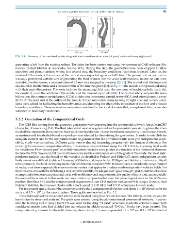
FIG. 5.1 Geometry of the considered models along with their main dimensions: aorta (left panel) and carotid artery (right panel).
generating a loft from the existing splines. The latter has been carried out using the commercial CAD software Rhi-
noceros (Robert McNeel & Associates, Seattle, WA). During this step, the geometries have been cropped to allow
smoothed and planar surfaces where, in a second step, the boundary conditions have been imposed. Later on, the
obtained 3D models of the aorta and the carotid were exported again as IGES files. The geometrical reconstruction
was only performed with the aim of generating the fluid domain. For the vessel wall thickness, in fact, no data were
available. For this reason, a constant value of 1.5 mm was assigned to the aorta [20, 21]. The carotid wall thickness was
also found in the literature and a constant value of 0.6 mm was given [22]. In Fig. 5.1, the models are represented along
with their main dimensions. The aorta includes the ascending (AA) tract, the anonyma or brachiocephalic trunk (A),
the carotid (C) and the subclavian (S) outlets, and the descending trunk (DA). The carotid artery includes the main
bifurcation: the common carotid artery (CCA) divides into the external carotid artery (ECA) and internal carotid artery
(ICA). At the inlet and at the outlets of the models, 5-inlet and outlets diameter-long straight inlet and outlets exten-
sions were added for facilitating the hemodynamics and dumping the effect of the imposition of the flow and pressure
boundary conditions. These extensions were also considered in the solid domains that, as explained later, were also
subjected to boundary conditions.
5.2.2 Generation of the Computational Grids
The IGES files coming from the geometry generation were imported into the commercial software Ansys IcemCFD
(Ansys Inc., Canonsburg, PA). The fluid tetrahedral mesh was generated for the presented cases starting from the inter-
nalshellthat represents the numerical fluid-solid interface domain. Due tothe intrinsiccomplexity ofthe human vessels,
an unstructured tetrahedral-based morphology was selected for discretizing the geometries. In order to establish the
adequate element size for the computations and to guarantee that the provided results were grid-independent, a sen-
sitivity study was carried out. Different grids were evaluated, increasing progressively the number of elements. For
reducing the necessary computational time, this analysis was performed using the CFD, that is, imposing rigid walls
for the arteries. Flow velocity profiles at different arterial sections were plotted as a function of the number of elements.
Because the WSS plays a central role in atherogenesis and its evaluation is one of the goals of this study, the mesh inde-
pendence analysis was also based on this variable. As detailed in Prakash and Ethier [23], mesh-independent velocity
fieldsarenotverydifficult toobtain.However,WSSfields,and,inparticular,WSSgradientfieldsaremuchmoredifficult
to be accurately resolved. Achieving mesh-independence in computed WSS fields requires a considerably large number
of nodes, and shows appreciable errors even on meshes that appear to produce mesh-independent velocity fields. For
these reasons, and with the WSS beinga verysensible variable, the adequate or “goodenough” grid should be selectedas
a compromise between computational costs, solver efficiency and requirements, the quality of input data, and especially
the needs of the scientist. In this work, we have made a compromise between the percentage of error on the WSS com-
putation (less than 8%) and the computational requirements (one CFD analysis took about 96 h using a 16-node, Dual
Nehalem (64 bits), 16-processor cluster with a clock speed of 2.33 GHz and 32 GB of memory for each node).
6
For the present study, the number of elements of the fluid computational meshes is of about 1 10 elements for the
6
aorta and 0.5 10 for the carotid artery. These grids are depicted in Fig. 5.2.
The solid models of the considered arteries were meshed using hexahedral elements. The latter is, in fact, usually the
best choice for structural analysis. The grids were created using the aforementioned commercial software. In partic-
ular, the blocking tool of Ansys IcemCFD was used for building “O-Grid” structures inside the arterial volume. Both
considered arteries were first divided into subvolumes in which structured “O-Grid” blocks have been inserted. The
6
6
computational grids used for the solid domains, shown in Fig. 5.2, are composed of 0.2 10 and 0.1 10 hexahedral
I. BIOMECHANICS