Page 88 - Advances in Biomechanics and Tissue Regeneration
P. 88

5.2 FINITE ELEMENT MODELING OF THE HUMAN BLOOD VESSELS                 83

           network in which we predicted physiological blood flow and pressure waveforms. This model consists of two parts:
           the large arteries (for this study, separately the aorta and the carotid artery) and the small arteries. In both, the
           blood flow and pressure are calculated using the incompressible axisymmetric Navier-Stokes equations for a Newto-
           nian fluid. A one-dimensional (1D) model is obtained by integrating these equations over the cross-sectional area of
           each vessel [24, 25].

           5.2.3.3 The Vascular Fractal Network
              As commented, the small arteries were modeled as a binary asymmetric-structured tree in which each vessel was
           assumed as a straight compliant segment. For computing the fractal tree, the relevant parameters are radii, bifurcation
           relationships, asymmetry, area ratios, lengths, and compliance. The vascular network resulted in a series of bifurcating
           segments composed of a parent and daughter vessels, as shown in Fig. 5.2. Asymmetry factors α and β guide the scal-
           ing of each parent vessel in two daughter vessels according to:

                                                             i j i
                                                        r i, j ¼ α β r root :                                (5.2)
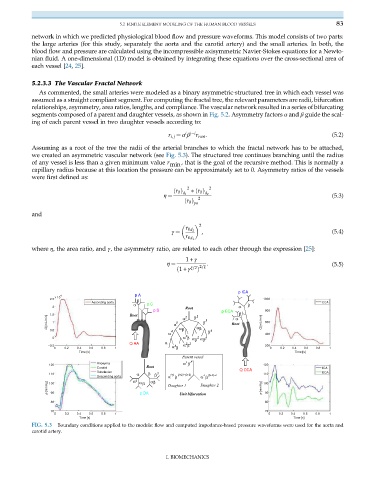
           Assuming as a root of the tree the radii of the arterial branches to which the fractal network has to be attached,
           we created an asymmetric vascular network (see Fig. 5.3). The structured tree continues branching until the radius
           of any vessel is less than a given minimum value r min , that is the goal of the recursive method. This is normally a
           capillary radius because at this location the pressure can be approximately set to 0. Asymmetry ratios of the vessels
           were first defined as:
                                                              2      2
                                                             d 1    d 2
                                                          ðr 0 Þ  + ðr 0 Þ
                                                                  2
                                                      η ¼                                                    (5.3)
                                                             ðr 0 Þ pa
           and
                                                                  2

                                                             r 0d 2
                                                                   ,                                         (5.4)
                                                         γ ¼
                                                             r 0d 1
           where η, the area ratio, and γ, the asymmetry ratio, are related to each other through the expression [25]:
                                                             1+ γ
                                                                    :
                                                       η ¼                                                   (5.5)
                                                           ð1+ γ ξ=2 2=ξ
                                                                 Þ
                                                                               p ICA
                     4                       p A
                   x 10
                 2.5                          β                                        1000
                               Ascending aorta   p C                                                      CCA
                  2                          α               Root              α  β
                                                   p S                   p ECA  β      800
                Q [mL/min] 1.5 1                          α 3  α 2  β 2  β  3  Root   Q [mL/min]  600
                                           Root
                                                                              α
                 0.5                                     4  α β  α β  β  4
                                                        α                              400
                                                              2
                  0                                          α β α β  2  α β 2
                                           Q AA        α      2 2
                 –0.5                                    α β  α β                      200
                                                          3
                   0  0.2  0.4  0.6  0.8  1                                              0  0.2  0.4  0.6  0.8  1
                           Time [s]                                                              Time [s]
                                                            Parent vessel
                                 Anonyma                     α  i β  ji
                 120                                                                   120
                                 Carotid         Root                          Q CCA                      ICA
                                 Subclavian                                                               ECA
                 110                          α  β  β  2  i+j  (j+1)−(i+1)  i  (j+1)−i  110
                                 Descending aorta       α  β      α β
                                            α 2  α β  α β                              100
                p [mmHg]  90                   p DA     Daughter 1  Daughter 2        p [mmHg]  90
                 100
                                                            Unit bifurcation
                  80                                                                   80
                  70                                                                   70
                   0  0.2  0.4  0.6  0.8  1                                              0  0.2  0.4  0.6  0.8  1
                           Time [s]                                                              Time [s]
           FIG. 5.3  Boundary conditions applied to the models: flow and computed impedance-based pressure waveforms were used for the aorta and
           carotid artery.
                                                       I. BIOMECHANICS
   83   84   85   86   87   88   89   90   91   92   93