
Page 90 - Advances in Biomechanics and Tissue Regeneration
P. 90
5.2 FINITE ELEMENT MODELING OF THE HUMAN BLOOD VESSELS 85
5.2.5 Boundary Conditions for the Solid Domain
Some parts of the structural domains of the considered arterial models were clamped to avoid the movement as
a rigid body. In particular, the extremities of the inlet and outlet extensions were constrained by fixing their surface
rotations and axial translations, allowing only in-plane movement of each section. In the aorta, the mesh nodes of
the extremity of the ascending aorta extension and that of the antonyma, subclavian, carotid, and descending trunk
extensions were fixed. In the carotid artery, no axial or transaxial motion was permitted at the extremities of the CCA,
ICA, and ECA extensions. These conditions, even nonphysiological as the inlet and outlets should theoretically
be allowed to deform radially for simulating the arterial tethering, are usually assumed in the literature of the
field [10, 11, 18].
5.2.6 Blood Flow Modeling
Arterial blood flow was modeled as laminar [30–32] incompressible and non-Newtonian. In particular, we utilized
the Carreau-Yasuda model for modifying the blood viscosity as a function of the shear rate. The constitutive equation
that represents this model is given by the following equation:
n 1
a a (5.10)
∞
∞
0
μ ¼ μ + ðμ μ Þ 1+ λ_γðÞ½ ,
where μ 0 ¼ 0.056 is the viscosity at zero shear rate expressed in [Pa s], μ ¼ 0:00345 is the viscosity for an infinity shear
∞
rate expressed in [Pa s], λ ¼ 3.313 is the relaxation time expressed in [s], n ¼ 2 is the power exponent, and a ¼ 0.64 is the
3
Yasuda exponent [33]. The blood density was set to 1060 kg/m .
5.2.7 Quantification of Hemodynamic Indices
Because the WSSs are biomarkers for vascular diseases, from the simulated models, we have evaluated velocity,
pressure, and the most common WSS-related indicator such as time average wall shear stress (TAWSS). All hemody-
namic variables were registered at every time step. The TAWSS was computed starting from the instantaneous WSS
vector τ w registered at each time instant of the cardiac cycle period T. The TAWSS for pulsatile flow represents the
!
spatial distribution of the tangential, frictional stress caused by the action of blood flow on the vessel wall temporally
averaged on the entire cardiac cycle. It is often used in the computational cardiovascular hemodynamics [16, 18, 30, 31],
and it can be calculated by integrating the WSS vector over the cardiac cycle:
1 Z T
j τ w jdt (5.11)
!
TAWSS ¼
T 0
5.2.8 Structural Modeling
5.2.8.1 Aortic Structural Modeling
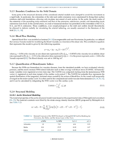
The material properties of the aortic structural model were based on the experimental data of Holzapfel and coworkers
[34, 35]. The material constants were fitted by the strain energy density function (SEDF) proposed by Holzapfel et al.
(see Table 5.2):
X h h i i
k 1 2 2
ψ ¼ μ½I 1 3 + exp k 2 ½1 ρ½I 1 3 + ρ½I i 1 1 , (5.12)
2k 2
i¼4,6
TABLE 5.2 Material Constants of the SEDF Developed in Holzapfel [34] Used for Modeling the
Adventitia, the Media, and the Intima Layer of the Aorta
μ [kPa] k 1 [kPa] k 2 [2] ρ [2]
Adventitia 1.8 7.03 6.04 0.15
Media 12.8 17.37 34.92 0.17
Intima 12.8 17.37 34.92 0.17
I. BIOMECHANICS