
Page 174 - Advances in Renewable Energies and Power Technologies
P. 174
3. Smart Maximum Power Point Tracker Under Partial Shading Conditions 147
0
-200
Shaded Cell Power (W) -600
-400
-800
-1000
-1200 1000
-400 -300 500
-200
-100 Radiation of Shaded
0 0
Shaded Cell Voltage (V) Cell (W/m2)
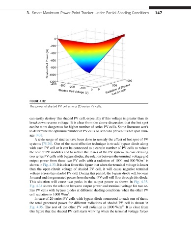
FIGURE 4.32
The power of shaded PV cell among 20 series PV cells.
can easily destroy this shaded PV cell, especially if this voltage is greater than its
breakdown reverse voltage. It is clear from the above discussion that the hot spot
can be more dangerous for higher number of series PV cells. Some literature work
to determine the optimum number of PV cells on series to prevent its hot spot dam-
age [40].
A wide range of studies have been done to remedy the effect of hot spot of PV
systems [75,76]. One of the most effective technique is to add bypass diode along
with each PV cell or it can be connected to a certain number of PV cells to reduce
the cost of PV modules and to reduce the losses of the PV system. In case of using
two series PV cells with bypass diodes, the relation between the terminal voltage and
2
output power from these two PV cells with a radiation of 1000 and 500 W/m is
shown in Fig. 4.33. It is clear from this figure that when the terminal voltage is lower
than the open-circuit voltage of shaded PV cell, it will cause negative terminal
voltage across this shaded PV cell. During this period, the bypass diode will become
forward and the generated power from the other PV cell will flow through this diode.
This situation will cause two peaks in the output power as shown in Fig. 4.33.
Fig. 4.34 shows the relation between output power and terminal voltage for two se-
ries PV cells with bypass diodes at different shading conditions when the other PV
2
cell radiation is 1000 W/m .
In case of 20 series PV cells with bypass diode connected to each one of them,
the total generated power for different radiations of shaded PV cell is shown in
2
Fig. 4.35. The rest of the other PV cell radiation is 1000 W/m . It is clear from
this figure that the shaded PV cell starts working when the terminal voltage forces