
Page 171 - Advances in Renewable Energies and Power Technologies
P. 171
144 CHAPTER 4 Performance of MPPT Techniques of Photovoltaic Systems
is the maximum
where I sens max is the maximum PV current to be sensed and V adc max
input voltage accepted by ADC circuits. The Op-Amp device used in the PV current
sensing circuit is the same as the device used in PV voltage-sensing circuit.
The terminals of the current sensor ACS754XCB-150 must be connected in se-
ries with the PV array as shown in Fig. 4.27. The current passing through the PV
array must enter the sensor from its IPþ terminal and exit the sensor from its IP
terminal. It is suggested to connect sensor’s IPþ terminal to the PV array positive
terminal and the senor’s IP terminal to one of boost’s coil terminal.
3. SMART MAXIMUM POWER POINT TRACKER UNDER
PARTIAL SHADING CONDITIONS
3.1 PARTIAL SHADING EFFECT
PV cells should be connected in parallel and series to increase the current and
voltage, respectively, to be suitable for the load. Partial shading occurs when one
or more PV cells in the PV array are exposed to lower radiation than the rest of
the PVarray. If partial shading occurs to one or more of series PV cells, it will force
the partial shading PV cell to work with current higher than the generated current
and it will act as a load for the other PV cells. If the current flow in the shaded
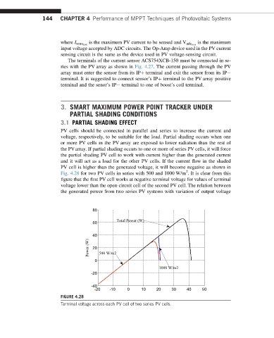
PV cell is higher than the generated voltage, it will become negative as shown in
2
Fig. 4.28 for two PV cells in series with 500 and 1000 W/m . It is clear from this
figure that the first PV cell works at negative terminal voltage for values of terminal
voltage lower than the open-circuit cell of the second PV cell. The relation between
the generated power from two series PV systems with variation of output voltage
80
Total Power (W)
60
40
Power (W) 20 500 W/m2
0
1000 W/m2
-20
-40
-20 -10 0 10 20 30 40 50
FIGURE 4.28
Terminal voltage across each PV cell of two series PV cells.