
Page 167 - Advances in Renewable Energies and Power Technologies
P. 167
140 CHAPTER 4 Performance of MPPT Techniques of Photovoltaic Systems
4N32
In out
+ 7815 6 1
24
10uF 10uF
220V 0 5 2
24
– 4 3
FIGURE 4.22
The circuit diagram of isolating circuit.
In out +15 +15V
7815
24 + + R3
100uF 10uF
220V 0 0
+ 100uF + R4
10uF
24 10nF
7915 –15V
In out –15
R1 +15V
100k
Ri
R2 741
–15V +15V
100Ω
+15V 741
6
100kΩ –15V
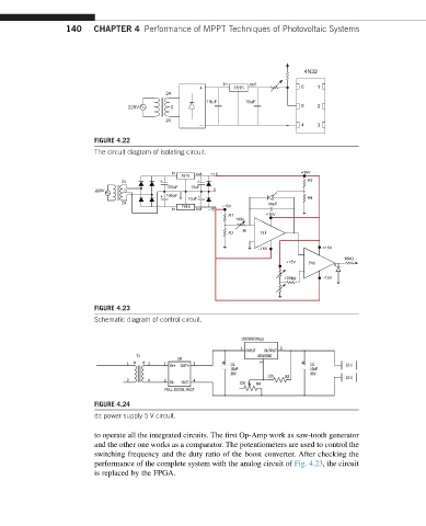
FIGURE 4.23
Schematic diagram of control circuit.
FIGURE 4.24
dc power supply 5 V circuit.
to operate all the integrated circuits. The first Op-Amp work as saw-tooth generator
and the other one works as a comparator. The potentiometers are used to control the
switching frequency and the duty ratio of the boost converter. After checking the
performance of the complete system with the analog circuit of Fig. 4.23, the circuit
is replaced by the FPGA.