
Page 166 - Advances in Renewable Energies and Power Technologies
P. 166
2. PV System Under Nonshading Conditions 139
100 SOC H
soc 99.5
99 SOC L
0 100 200 300 400 500 600
V battery 71.985
71.99
71.98
0 100 200 300 400 500 600
30
20 Battery Current
I battery 10
0
-10
0 100 200 300 400 500 600
40
I load 20 Load Current
0
0 100 200 300 400 500 600
10
5
I PV
0
0 100 200 300 400 500 600
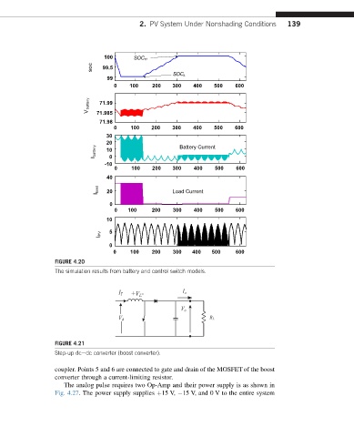
FIGURE 4.20
The simulation results from battery and control switch models.
+V L- I o
I T
V o
V d R L
FIGURE 4.21
Step-up dcedc converter (boost converter).
coupler. Points 5 and 6 are connected to gate and drain of the MOSFET of the boost
converter through a current-limiting resistor.
The analog pulse requires two Op-Amp and their power supply is as shown in
Fig. 4.27. The power supply supplies þ15 V, 15 V, and 0 V to the entire system