Page 287 - Advances in Renewable Energies and Power Technologies
P. 287

260    CHAPTER 8 Hybrid PV/Batteries Bank/Diesel Generator


                         FIGURE 8.1
                         Block diagram of a hybrid renewable energy system. U 1 and U 2 are switches.
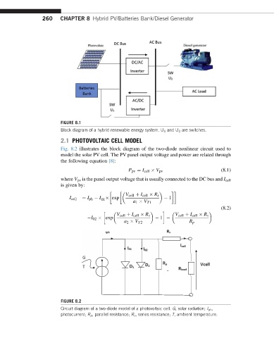
                         2.1 PHOTOVOLTAIC CELL MODEL
                         Fig. 8.2 illustrates the block diagram of the two-diode nonlinear circuit used to
                         model the solar PV cell. The PV panel output voltage and power are related through
                         the following equation [8]:

                                                    P pv ¼ I cell   V pv                (8.1)
                         where V pv is the panel output voltage that is usually connected to the DC bus and I cell
                         is given by:

                                                  V cell þ I cell   R s
                                 ¼ I ph   I   exp                   1
                            I cell
                                         01
                                                     a 1   V T1
                                                                                        (8.2)

                                               V cell þ I cell   R s  V cell þ I cell   R s
                                    I 02   exp                  1
                                                  a 2   V T2               R p


                         FIGURE 8.2
                         Circuit diagram of a two-diode model of a photovoltaic cell. G, solar radiation; I ph ,
                         photocurrent; R p , parallel resistance; R s , series resistance; T, ambient temperature.
   282   283   284   285   286   287   288   289   290   291   292