
Page 289 - Advances in Renewable Energies and Power Technologies
P. 289
262 CHAPTER 8 Hybrid PV/Batteries Bank/Diesel Generator
diagram of a battery cell. The battery dod parameter value is related to the battery
capacity by:
C R
dod ¼ (8.6)
C p
where
K
C p ¼ I T (8.7)
B
K is the Peukert coefficient that equals to 1.12, and T is the constant current
discharge time. The instantaneous capacity of the battery is given by:
DC R I B K
¼ (8.8)
Dt 3600
where the battery current I B is given by:
P B
I B ¼ (8.9)
V B
where P B is the power supplied by the battery to the load.
2.3 DIESEL GENERATOR MODEL
Many models have been published in the literature to model the DG [10e14]. Prac-
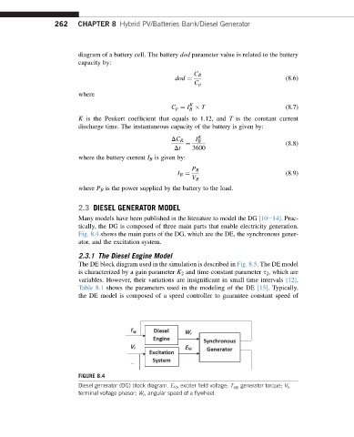
tically, the DG is composed of three main parts that enable electricity generation.
Fig. 8.4 shows the main parts of the DG, which are the DE, the synchronous gener-
ator, and the excitation system.
2.3.1 The Diesel Engine Model
The DE block diagram used in the simulation is described in Fig. 8.5. The DE model
is characterized by a gain parameter K 2 and time-constant parameter s 2 , which are
variables. However, their variations are insignificant in small time intervals [12].
Table 8.1 shows the parameters used in the modeling of the DE [15]. Typically,
the DE model is composed of a speed controller to guarantee constant speed of
FIGURE 8.4
Diesel generator (DG) block diagram. E fd , exciter field voltage; T sg , generator torque; V t ,
terminal voltage phasor; W r , angular speed of a flywheel.