
Page 290 - Advances in Renewable Energies and Power Technologies
P. 290
2. Hybrid Renewable Energy System Modeling 263
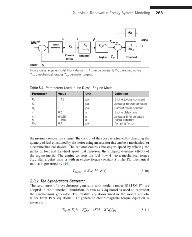
FIGURE 8.5
Typical diesel engine model block diagram. H 1 , inertia constant; K D , damping factor;
T mec , mechanical torque; T sg , generator torque;.
Table 8.1 Parameters Used in the Diesel Engine Model
Parameter Value Unit Definition
K 1 1.15 pu Engine torque constant
K 2 1 pu Actuator torque constant
K 3 1 pu Current driver constant
s 1 0.5 s Engine delay time
s 2 0.125 s Actuator time constant
1.666 s Inertia constant
H 1
0.1 pu Damping factor
K D
the internal combustion engine. The control of the speed is achieved by changing the
quantity of fuel consumed by the motor using an actuator that can be a mechanical or
electromechanical device. The actuator controls the engine speed by relating the
intake of fuel and flywheel speed that represent the complex dynamic effects of
the engine inertia. The engine converts the fuel flow ɸ into a mechanical torque
T mec after a delay time s 1 with an engine torque constant K 1 . The DE mechanical
motion is governed by [16]:
T ¼ K 1 e s 1 s fðsÞ (8.10)
mec ðsÞ
2.3.2 The Synchronous Generator
The parameters of a synchronous generator with model number E1S13M F/4 are
adopted in the numerical simulation. A two-axis dq-model is used to represent
the synchronous generator. The relative equations used in the model are ob-
tained from Park equations. The generator electromagnetic torque equation is
given as:
00 00 0 00
T sg ¼ E I d þ E I q ðX d X qÞI d I q (8.11)
q
d