
Page 288 - Advances in Renewable Energies and Power Technologies
P. 288
2. Hybrid Renewable Energy System Modeling 261
where ɑ 1 and ɑ 2 are the diode ideal constants, V T1 and V T2 are the thermal voltages of
a PV module that has many cells, while the cell photocurrent I ph as a function of tem-
perature and irradiance is given by:
G
þ a SC DT (8.3)
I ph ¼ I ph STC
G STC
where a sc is the temperature coefficient for short circuit current and DT is defined as:
ðKÞ. (8.4)
DT ¼ T A T STC
The diodes D 1 and D 2 saturation currents are given by:
þ a SC DT
I pv STC
I o ¼ I o ¼ (8.5)
ð1;2Þ exp½½ðV oc þ b oc DTÞ V T 1
STC
Maximum power point trackers are mainly used to enable operating the PV panel
at maximum power generation [9]. Typically, many solar cells are connected in se-
ries to increase the PV panel DC output voltage and in parallel to increase its
achieved current. Then, PV panels are connected in strings of series and parallel
combinations to produce certain amount of power in Watts that would satisfy the
load needs. However, this produced power will not satisfy the load requirements
every hour during the day because of limitations in available sun radiation. There-
fore, supplement energy sources are installed in conjunction with the PV subsystem.
2.2 LEAD-ACID BATTERY MODEL
Researchers are investigating different energy storage solutions to enable storing
excess energy produced by renewable sources [1]. Stored energy can be used dur-
ing periods when there is no energy generated by the PV subsystem. Lead-acid bat-
teries are used to store excess energy produced either by the PV solar system or by
the DG. Lead-acid batteries are chosen because of their lower initial cost and wide
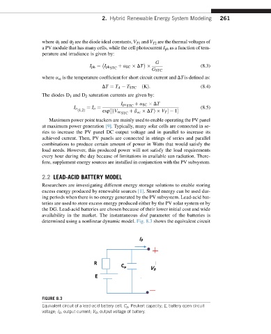
availability in the market. The instantaneous dod parameter of the batteries is
determined using a nonlinear dynamic model. Fig. 8.3 shows the equivalent circuit
FIGURE 8.3
Equivalent circuit of a lead-acid battery cell. C p , Peukert capacity; E, battery open circuit
voltage; I B , output current; V B , output voltage of battery.