
Page 291 - Advances in Renewable Energies and Power Technologies
P. 291
264 CHAPTER 8 Hybrid PV/Batteries Bank/Diesel Generator
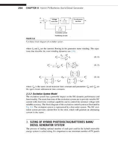
FIGURE 8.6
Functional block diagram of excitation system.
where I d and I q are the currents flowing in the generator stator winding. The equa-
tions that describe the rotor winding dynamics are [16]:
X q X 00 q
00
E ¼ I q (8.12)
d
1 þ s s
00
q0
!
0
1 X X 00
00 0 d d
E ¼ E I d (8.13)
q
q
1 þ s s 1 þ s s
00
00
d0 d0
!
x d x 0
d
0
1 x x 00 d
d
0 00
q q
E ¼ ! E fd þ ! E (8.14)
x d x 00 x d x 00
d þ s s d þ s s
0
0
0
x x 00 d0 x x 00 d0
0
d d d d
where s 0 is the open circuit transient time constant and parameters s 00 and s 00 are
d0 d0 q0
the open circuit subtransient time constants.
2.3.3 Excitation System Model
The excitation system has a powerful impact on the DG dynamic performance and
functionality. The main functions of the excitation system are to provide variable DC
current with short time overload capability and to control the terminal voltage with
suitable accuracy. The block diagram of the excitation control system is illustrated in
Fig. 8.6. The excitation system is represented by a first-order system. The DC exci-
tation system provides current flow to the rotor, which will generate an alternating
current in the stator.
3. SIZING OF HYBRID PHOTOVOLTAIC/BATTERIES BANK/
DIESEL GENERATOR SYSTEM
The process of finding optimal number of each part used in the hybrid renewable
energy system is called sizing. It is important to use minimum number of PV panels