
Page 340 - Advances in Renewable Energies and Power Technologies
P. 340
3. Photovoltaic Irrigation Systems Components 313
400
η = 74,37%
50 Hz
350
η = 76,19%
300
45 Hz η = 76,7%
250 40 Hz η = 74,48%
Head (m) 200 35 Hz
150 η = 66,5%
30 Hz
100
25 Hz
20 Hz
50
0
0 2 4 6 8 10 12 14
Discharge (l/seg)
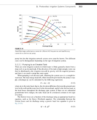
FIGURE 9.18
Head-Discharge performance curves for different AC frequencies and isoefficiency
curves for a commercial pump.
pump but also the irrigation network system curve must be known. Two different
cases can be distinguished depending on the type of irrigation system.
3.2.2.1 Pumping to an Elevated Tank
There are some irrigation systems in which water is lifted, generally drawn from a
deep well, to an elevated tank. If the elevation of this tank is high enough, water can
then be distributed to the irrigation network by gravity with the required pressure,
and there is no need to pump the water again.
When pumping to an elevated tank, obtaining the system curve is a straightfor-
ward task. The total energy head (H), which should be provided by the pump to sup-
ply a discharge Q, can be calculated by the following expression:
H ¼ Dz þ hf (9.12)
where Dz is the static head, that is, the elevation difference between the groundwater
level in the well and the water level in the elevated tank, and hf is the friction head, or
the head losses throughout the discharge pipe system. If there are no substantial
groundwater level changes, the static head can be considered constant in this type
of system.
The friction losses are a function of the discharge using an appropriate head loss
equation, such as the DarcyeWeisbach equation. The relationship between the
friction losses and the discharge using a generic head loss equation is given in
Eq. (9.13).
hf ¼ R s $Q m (9.13)