Page 345 - Advances in Renewable Energies and Power Technologies
P. 345

318    CHAPTER 9 Design Principles of Photovoltaic Irrigation Systems


                            Another complementary way to regulate the system and to optimize the use of
                         the generated energy for irrigating the crop is to design more than one irrigation
                         sector. When the farm is divided into a number of sectors (n s ) greater than 1, the
                         discharge and power needed to irrigate each sector can be obtained by dividing
                         the maximum discharge and the maximum power by n s .
                            In this case, the system can start irrigating with a shaft power that is n s times
                         lower than when only one sector is considered. Two different strategies can be
                         applied in this type of system:

                         1. To irrigate with only one irrigation sector in operation
                         2. To irrigate with multiple irrigation sectors in operation simultaneously
                            In the first scenario, only one pump is required as the same pump would be used
                         to irrigate all the irrigation sectors. In the second scenario, the number of pumps
                         would have to be equal to the number of sectors that are irrigated simultaneously.
                            Generalizing, when a number “n j ” of sectors out of n s are operating simulta-
                         neously, the net power generated by the PV system (P) must be distributed among
                         the n j pumps in operation (P i ¼ P/n j ). Thus, the total discharge of the system is rep-
                         resented by Eq. (9.27):

                                           P   P m                            9
                                     aÞ If   <    0 Q i ¼ 0                   >
                                                                              >
                                                                              >
                                           n j  n s                           >
                                                                              >
                                                                              >
                                                                              >
                                                                              >
                                                                              >
                                                                          !
                                                                           1=3 >
                                                                              =
                                           P m  P   P M         Q M  P i n s
                                     bÞ If             0 Q i ¼ n j                     (9.27)
                                           n s  n j  n s         n s  n j P M  >
                                                                              >
                                                                              >
                                                                              >
                                                                              >
                                                                              >
                                           P   P M       Q M                  >
                                                                              >
                                     cÞ If   >    0 Q i ¼   $n j              >
                                                                              >
                                                                              ;
                                           n j  n s       n s
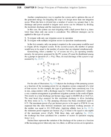
                            For the sake of illustration, Fig. 9.20 depicts the discharge of the pumping system
                         as a function of the incoming power for an irrigation system composed of a total
                         of four sectors. In this example, the type of greenhouse farm considered was 1 ha
                                                                                   2
                         in size, using emitters with a discharge equal to 3 L/h and 2 emitters/m , which is
                         a very common arrangement in greenhouse irrigation systems in the south of Spain.
                         This results in a total discharge per hectare (Q M ) equal to 60,000 L/h or 16.67 L/s.
                         The total head (H M ) assumed for this maximum discharge is 40 m (including
                         the three terms in Eq. 8). The pumping efficiency has been considered equal to
                         0.75. The maximum power (P M ) per hectare proves to be equal to 8720 W. It was
                         supposed that the ratio between minimum and maximum working pressure of
                         the emitter was equal to 1/4 (5/20 m/m). Applying affinity laws in Eq. (9.19),
                         the minimum power required per hectare (P m ) is found to be equal to one-eighth
                         of the maximum power (P M /8). With these data, and applying Eq. (9.22),
                         the discharge has been calculated for a number of sectors in operation ranging
                         from 1 to 4.
                            Dashed lines represent the variation of the discharge of the system as a function
                         of the incoming power when only one, two, three, or all four sectors are in operation.
   340   341   342   343   344   345   346   347   348   349   350