
Page 366 - Advances in Renewable Energies and Power Technologies
P. 366
4. The Vector Control 339
Photovoltaic
panel
+ PI + - Inverter
-
p
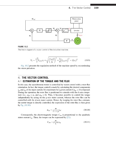
FIGURE 10.2
The block diagram of a scalar control of the induction machine.
p s ffiffiffiffiffiffiffiffiffiffiffiffiffiffiffiffiffiffiffiffiffiffiffiffiffiffiffiffiffiffiffiffiffiffiffiffiffiffiffiffiffiffiffiffiffiffiffiffiffiffiffiffiffiffiffiffiffiffiffiffiffiffiffiffiffi
ffiffiffi
2
2 v s0 f s 2 2 2
r
r
V s ¼ I sðreÞ s þ þ I sðreÞ s ðI s r s Þ (10.9)
3 f b 9
Fig. 10.2 presents the regulation method of the machine speed by reconstituting
the stator pulsation.
4. THE VECTOR CONTROL
4.1 ESTIMATION OF THE TORQUE AND THE FLUX
In this case, the asynchronous motor is controlled by vector control with a rotor flux
orientation. In fact, the torque control is made by calculating the desired components
i qs and i ds of the stator current. It is maximum for a given current if 4 qr ¼ 0is imposed.
During the operation, the rotor flux is positioned to coincide with the d-axis compo-
nent (i.e., 4 dr ¼ 4 r and 4 qr ¼ 0). Thus, it becomes possible to control the torque
independently by acting on the q-axis stator current, whereas the rotor flux can be
controlled with the d-axis stator current. Hence, by keeping the rotor flux constant,
the motor torque is directly controlled, the expression of the rotor flux is then given
by Eq. (10.10):
m
4 rd ¼ i sd (10.10)
1 þ s r s
Consequently, the electromagnetic torque C em is proportional to the quadratic
stator current i sq . Then, the torque can be expressed by [23]:
m
C em ¼ p 4 i sq (10.11)
r
l r